
Part positioning and assembly process for creep sensitive material

a technology of creep and assembly process, which is applied in the direction of washers, screws, load-modified fasteners, etc., can solve the problems of improper sealing and sealing leakage at the connection between the air intake manifold and the cylinder head of the internal combustion engine, and reduce the air flow. the effect of precise advanced positioning of parts and avoiding any deformation

Active Publication Date: 2013-11-05
MANN HUMMEL GMBH
View PDF21 Cites 2 Cited by
  • Summary
  • Abstract
  • Description
  • Claims
  • Application Information

AI Technical Summary

Benefits of technology

[0014]An object of the present invention is to provide a positioning and assembly method and apparatus for two parts at least one of which is molded from a creep sensitive material, such as to remedy these disadvantages, in particular to make it possible to obtain very precise advanced positioning of the parts to be assembled while avoiding any deformation of the material constituting these parts under the action of heat or tightening stresses.
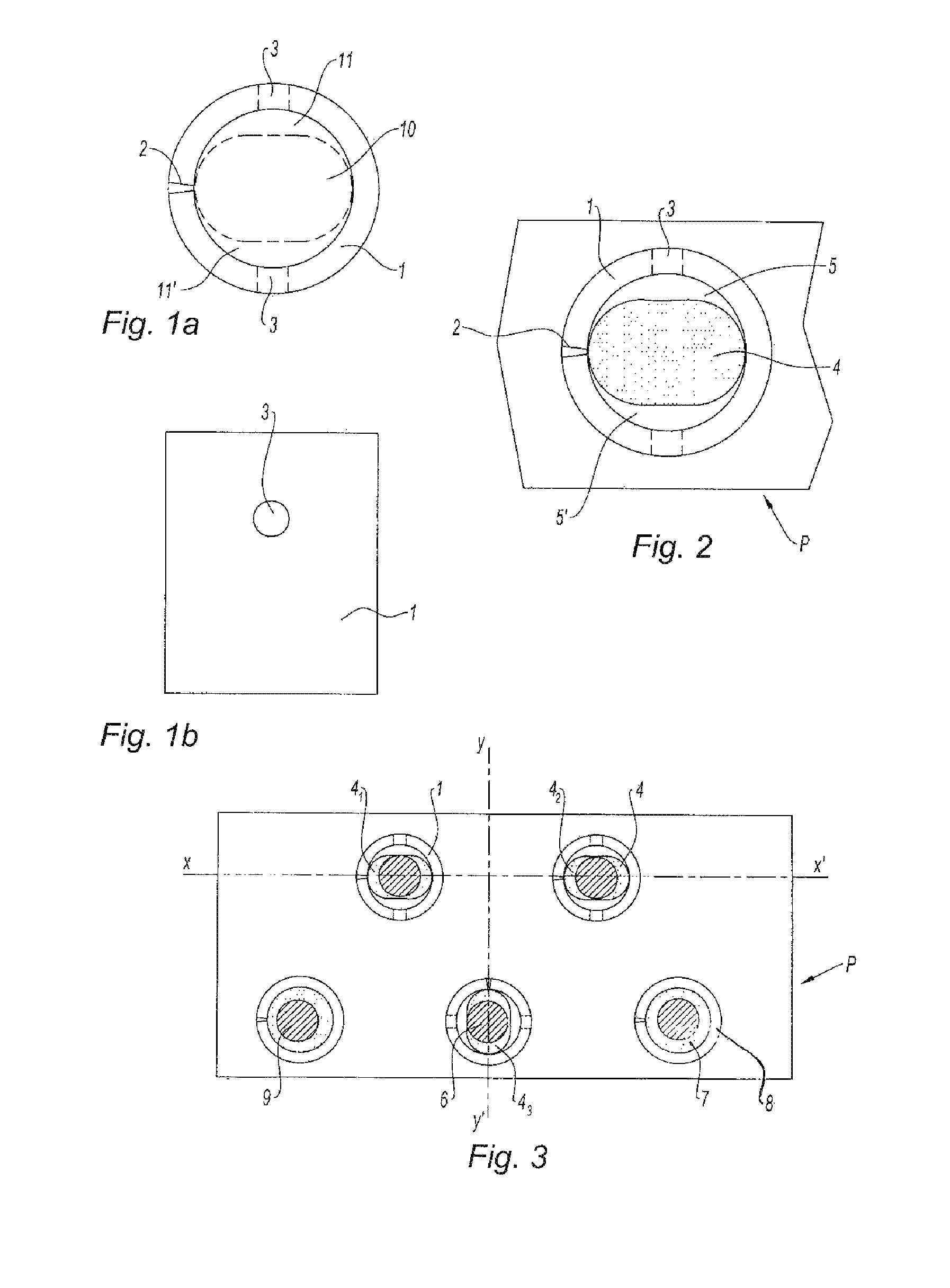
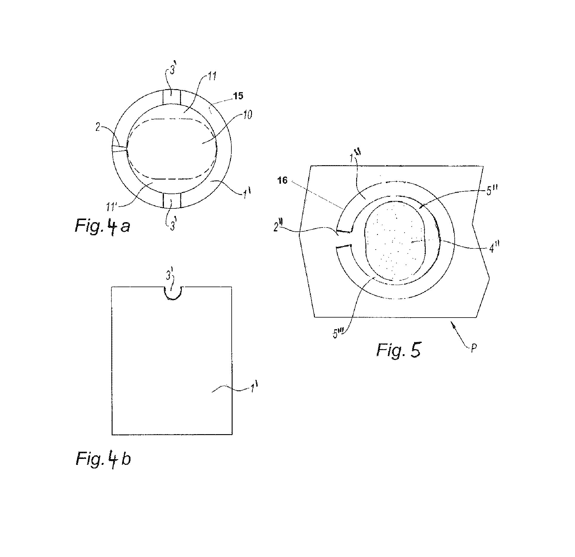
[0022]This insert constitutes a compression limiter which is configured to prevent the effects of plastic creep phenomena in the material surrounding the centering hole upon connection of the two parts.
[0026]Considering the preceding, the process conforming to the invention makes it possible to advantageously use annular inserts which serve as compression limiters and assembly screws or pins for very precisely positioning of the parts to be assembled relative to each other.
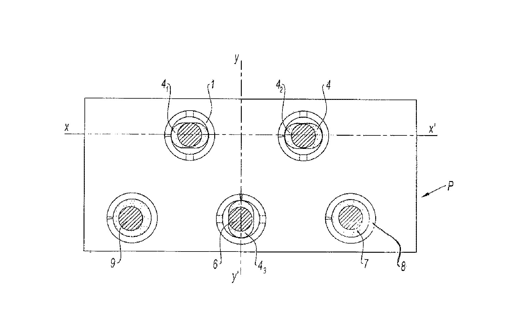
[0029]According to another preferred feature of the invention, the mold intended for the molding of the first part is equipped with at least three oblong spindles distributed thereon. This feature makes it possible to optimize the positioning of the two parts relative to each other in every direction.
[0030]In accordance with a further advantageous feature of the invention, the annular insert exhibits a slot formed in the wall of the insert in longitudinal direction, through which the creep sensitive material penetrates into the gap during molding. This slot is, for example, formed by a gap or distance between the two opposite ends of the rolled metal strip which is rolled to form the annular insert. The spindle is smaller in its larger diameter than the inside diameter of the annular insert so that the molded creep sensitive material can flow around the spindle during molding of the part and fill the gap between the spindle and the inner wall of the annular insert.
[0032]In the optimum case in which the spindles have an oblong section, the larger diameter of two of the spindles can advantageously be aligned along a first axis, whereas the larger diameter of the third spindle is perpendicular to this first axis and centered on the part as best as possible. Such a configuration makes it possible to obtain an optimum positioning of the two parts relative to each other prior to their assembly.

Problems solved by technology

In particular with air intake manifolds or other under the hood components, an improper alignment of the air ducts at the connecting flange on the engine can result in reduced air flow, increased pressure drop as well as possible improper sealing and seal leakage at the connection between the air intake manifold and the cylinder head of the internal combustion engine.
Such a positioning system has the disadvantage of creating fragile zones or weak points in the parts to be assembled (posts or pins) and also require the addition of supplemental elements such as centering holes which thereby increase the complexity and cost of the parts.
The implementation of such screws acting as centering posts has not however turned out to be satisfactory for use to the extent where they do not make it possible to obtain a sufficiently precise positioning.
Using attachment screws engaging with oblong compression limiters has also been proposed, but that leads to significant extra costs while also increasing the implementation complexity.
The use of oblong or oval compression limiters with a larger diameter and a traversing smaller diameter to the axis of the screw are seen as complex in production of creep sensitive parts as such compression limiters are difficult to handle when pressing them into the preformed receiving holes in the part.
Due to tolerance variations in the compression limiters and parts, the danger exists that the compression limiters may separate from the part during transport or handling.
Additional problems arise as the process of pressing the compression limiters into the receiving holes of the part may generate splinters or otherwise damage the receiving hole, resulting in a damaged part or a less than desired press fit.
Additional problems are from the use of both oblong and cylindrical compression limiters in the same parts these differing compression limiter geometries can be intermixed and thereby inserted into a receiving hole having geometry different from the compression limiter being inserted, resulting in damage to the part or a manufacturing defect.

Method used


Image

  • Part positioning and assembly process for creep sensitive material
  • Part positioning and assembly process for creep sensitive material
  • Part positioning and assembly process for creep sensitive material

Examples


Embodiment Construction

[0067]Before describing in detail embodiments that are in accordance with the present invention, it should be observed that the embodiments reside primarily in combinations of apparatus components methods related to a part positioning and alignment process and apparatus for creep sensitive materials, for example plastics. Accordingly, the apparatus components have been represented where appropriate by conventional symbols in the drawings, showing only those specific details that are pertinent to understanding the embodiments of the present invention so as not to obscure the disclosure with details that will be readily apparent to those of ordinary skill in the art having the benefit of the description herein.

[0068]In this document, relational terms such as first and second, top and bottom, and the like may be used solely to distinguish one entity or action from another entity or action without necessarily requiring or implying any actual such relationship or order between such entit...


PUM

PropertyMeasurementUnit
creep sensitiveaaaaaaaaaa
creepaaaaaaaaaa
volumeaaaaaaaaaa

Abstract

Disclosed is a method and apparatus for positioning and assembly of two or more parts wherein at least one of which is of a creep sensitive material. The method and apparatus enable very precise positioning of parts during assembly by holding a rough alignment with free play permitting finer alignment. Creep resistant annular inserts are molded into the part and provided with flow apertures to conduct plastic material into the annular insert bore. A spindle defined the geometry of a centering hole within the bore during molding. The annular inserts are operable as compression limiters to prevent deformation of the creep sensitive material under the action of heat or tightening stresses.

Description

CROSS REFERENCE TO RELATED APPLICATIONS[0001]This application claims the benefit under 35 USC 119 of foreign patent application 09 54 001 filed in France on Jun. 16, 2009, and which is hereby incorporated by reference in its entirety.TECHNICAL FIELD[0002]The subject of the present invention is a positioning and assembly process for two or more parts, in which in this procedure the parts are aligned and then joined. A first of these parts is made of a creep sensitive material such as for example a thermoplastic, a thermosetting material or an elastomer and it is made by a molding process, especially plastic injection molding. As for the second part, it can be made of any material whatsoever, plastic, composite, metal, etc.BACKGROUND OF THE INVENTION[0003]Filters in many technical domains (automobile industry, household appliances, computer hardware, etc.), parts, especially plastic injection molded parts must be very precisely positioned relative to each other before their assembly u...

Claims


Application Information

Patent Timeline
Patent Type & Authority Patents(United States)
IPC IPC(8): B32B3/24F16B31/02F16B43/00F16B43/02
CPCB29C45/1459B29C45/2628B29C45/14344B29C2045/14327B29K2705/00Y10T428/24182Y10T428/24058Y10T428/24339Y10T428/24314Y10T428/24025Y10T29/4998Y10T428/24322Y10T29/53135Y10T428/249923
Inventor WARNERY, STEPHANETREMBLAY, GUY
Owner MANN HUMMEL GMBH
Learn More