
System and method for electric load recognition from centrally monitored power signal and its application to home energy management

Inactive Publication Date: 2013-10-15
LEE KWANGDUK DOUGLAS
View PDF76 Cites 102 Cited by
  • Summary
  • Abstract
  • Description
  • Claims
  • Application Information

AI Technical Summary

Benefits of technology

The patent describes a method and device for managing energy in a home using a power sensor. The sensor collects data, which is then analyzed to determine detailed information about energy usage. This analysis can be done locally at the sensor or other devices in the home, or at servers in the cloud. The platform can provide information to users through various interfaces, such as web, mobile, email, and phone calls. The technical effect of this patent is a more efficient and effective way to manage energy in homes, allowing for better cost savings and better utilization of electricity.

Problems solved by technology

That is, the full-instrumentation approach has been found to be too expensive for many home owners and that pay-back may take longer than 10 years.
However, certain limitations of such approach are as follows, in no particular order:With transient recognition, an electric load can be ‘detected’.
However, its power consumption is difficult to estimate, unless power consumption is constant right after the turn-on transient.Faster sampling, e.g. greater than or equal to 1 Hz, is required to recognize a transient pattern, implying this type of algorithm can not be run with meter level data as most meter chips output power data at approximately 1 Hz internally.
The number of required pattern exemplars can be prohibitively enormous, as different appliances, different makers / models and different usage create different transient patterns.

Method used


Image

  • System and method for electric load recognition from centrally monitored power signal and its application to home energy management
  • System and method for electric load recognition from centrally monitored power signal and its application to home energy management
  • System and method for electric load recognition from centrally monitored power signal and its application to home energy management

Examples


embodiments

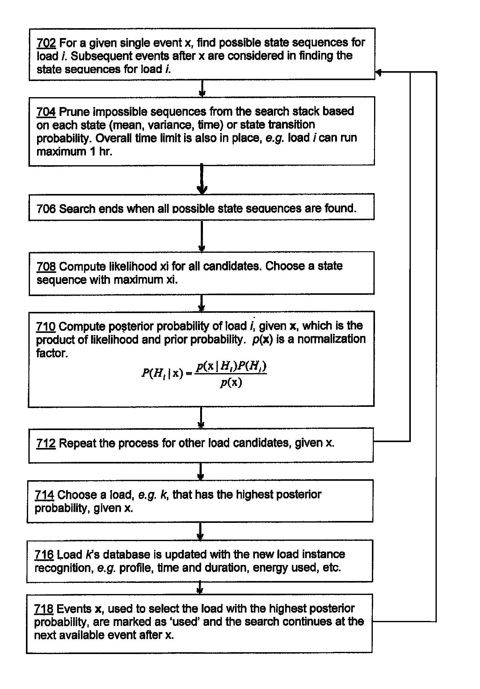
[0159]An embodiment provides a program flow in which the classification / search algorithm for recognizing appliances, i.e. loads, within a particular signal, i.e. events x, described hereinabove is used. It should be appreciated that other algorithms for recognizing particular loads for events can be contemplated and that the particular classification / search algorithm referred to hereinbelow is by way of example and is not meant to be limiting. Other types of pattern recognition algorithms may include neural network, wavelet analysis, spectral analysis, transient analysis, support vector machine (SVM), etc. Certain optimization algorithms can also be used for load disaggregation, such as least residue, integer programming, genetic algorithm, etc. For loads that have sensitivity to other parameters, e.g. HVAC loads with temperature, certain correlation techniques, e.g. regression, may be used to estimate their energy consumption from the whole building energy usage.

[0160]An embodiment...


PUM


Abstract

A method and apparatus are provided for a home energy management platform. The platform includes using a whole house power sensor or subset thereof. Data from the power sensor are analyzed using advanced statistical and machine learning techniques for extracting detailed usage information and generating specific energy saving measures, among other relevant information. In an embodiment, a gateway console is provided that has various communication capabilities. The gateway console may communicate with and control HAN devices. The gateway console may collect data from the power sensor as well as HAN devices and upload such collected data to servers for the analysis processing. Certain amounts of data processing and analysis may be performed at a server or at the local level, such as at the power sensor, gateway, or other HAN device, as well. The platform may include a user interface, such as web, mobile, email, mail, phone call, etc.

Description

BACKGROUND OF THE INVENTION[0001]1. Technical Field[0002]The invention relates to home energy management systems. More particularly, the invention relates to a method and apparatus for incorporating and applying advanced analytics into a home energy management system for providing detailed usage information and energy saving tips, among other relevant data.[0003]2. Description of the Background Art[0004]Home energy management is a newly emerging market with widespread deployment of smart grid infrastructure. A smart grid allows two-way flow of energy and information between an appliance, such as a refrigerator, and a controller, such as a processor residing on a smart meter or even on a server. As well, a smart grid allows two-way flow of information between smart meters and utilities.[0005]Smart Meter[0006]A smart meter is an advanced meter at a consumption site, can measure utility consumption, e.g. consumption of electricity, at the site and is in communication with the utility c...

Claims


Application Information

Patent Timeline
IPC IPC(8): G05D3/12
CPCH02J13/0086G06Q50/06Y02E40/76Y04S10/545Y04S40/128Y02B90/2669H02J2310/70H02J13/00028Y02B90/20H02J13/00002H02J13/00026Y04S10/30Y04S40/126Y02E60/00Y02E40/70Y04S10/50
Inventor LEE, KWANGDUK DOUGLAS
Owner LEE KWANGDUK DOUGLAS
Learn More