
Filter mosaic for detection of fugitive emissions

a filter mosaic and emission detection technology, applied in the field of filter mosaic for detection of fugitive emissions, can solve the problems of cumbersome approach that is not acceptable in modern color photography and cannot be acceptabl

Active Publication Date: 2013-10-15
HARRIS CORP
View PDF19 Cites 24 Cited by
  • Summary
  • Abstract
  • Description
  • Claims
  • Application Information

AI Technical Summary

Benefits of technology

The present invention provides a system and method for detecting and measuring a fugitive gas using a filter array and a solid state imaging array. The filter array includes at least two different filtering elements that transmit predetermined wavelengths of light to the gas for detection and identification. The system can detect the gas by measuring the concentration path length of the gas emission from the target. The system can also measure the gas concentration using a calibration constant. The invention can be used for identifying a plume of gas and has applications in various fields such as environmental monitoring and industrial process control.

Problems solved by technology

This cumbersome approach is not acceptable in modern color photography and need not be acceptable in remote sensing situations.

Method used


Image

  • Filter mosaic for detection of fugitive emissions
  • Filter mosaic for detection of fugitive emissions
  • Filter mosaic for detection of fugitive emissions

Examples


Embodiment Construction

[0039]The following description is directed in particular to elements forming a part of or associated with the present invention. It is understood that elements not specifically shown in the figures or described may take various forms known to those skilled in the art.

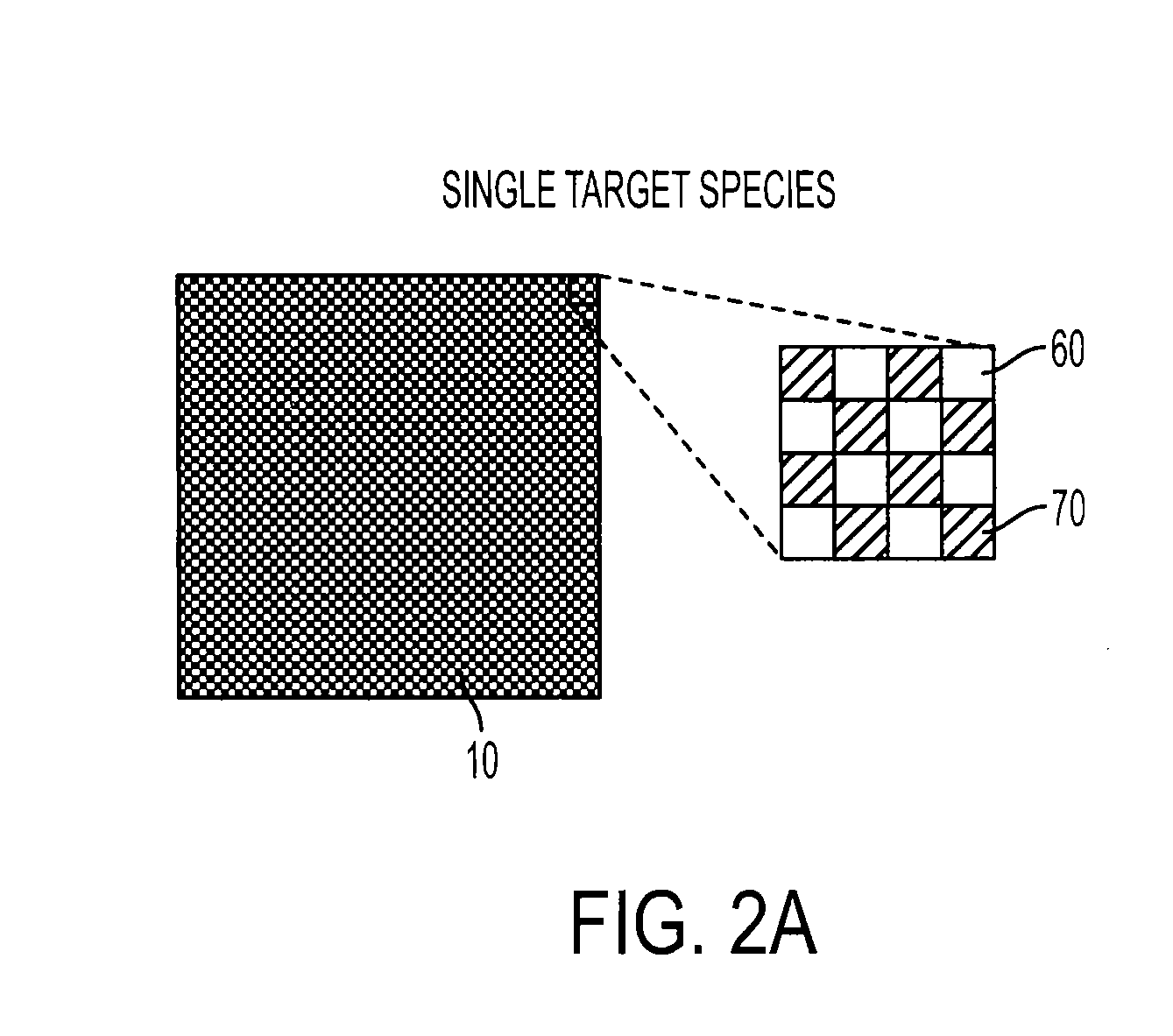
[0040]FIG. 1 is an exploded view illustrating an embodiment of the present invention. As shown, an imaging system includes a focal plane array (FPA) 20 overlaid in registration (or aligned) with a filter array 10. The filter array 10 and imaging array 20 are used together with a lens 30 to form and record an image 50 of a target 40. A processor, generally designated as 22, is coupled to the imaging array for processing image intensity data outputted by the pixels of FPA 20.

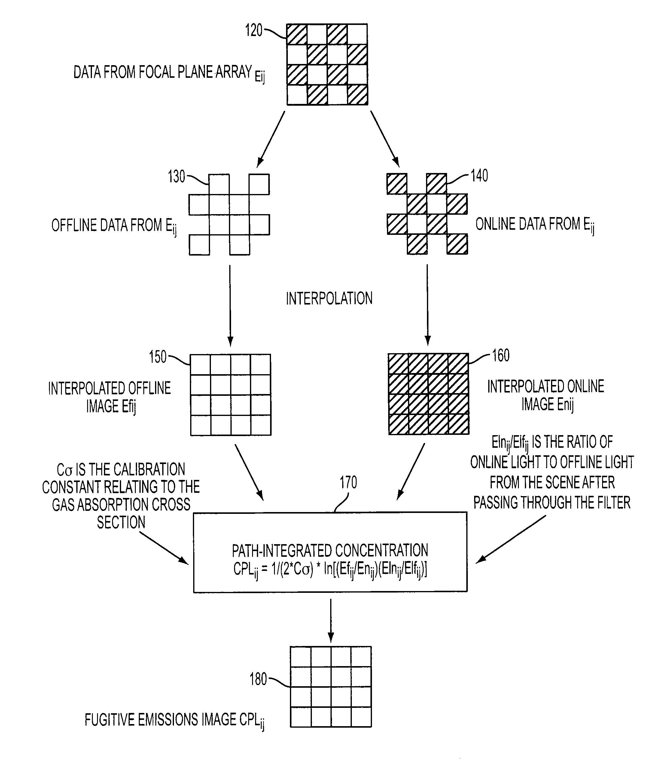
[0041]Each filter element may be aligned to cover one or more pixels of the FPA. This is shown in a magnified view of a 4×4 pixel sub-array and a 4×4 filter mosaic sub-array of FPA 20 and mosaic filter array 10, respectively, in FIG. 1. One filter el...


PUM

PropertyMeasurementUnit
thicknessaaaaaaaaaa
wavelengthaaaaaaaaaa
offline wavelengthaaaaaaaaaa

Abstract

A method and apparatus for quantitative and qualitative imaging of fugitive emissions of gas, vapors, or fumes are described. The apparatus includes a filter mosaic for placement in registration over an imaging focal plane array (FPA). The filter mosaic includes at least two filter elements providing transmission response functions for transmitting wavelengths of light corresponding to an absorption wavelength (online wavelength) and a non-absorption wavelength (offline wavelength) of the targeted fugitive emission. Also described is an image processing method for transforming a filtered image into an image of the targeted fugitive emission.

Description

FIELD OF THE INVENTION[0001]The present invention is related to a system and method for detecting fugitive emissions of fluid or gas in the atmosphere. More specifically, the present invention is related to remotely detecting fugitive emissions in the atmosphere using a combination of a filter mosaic and an imaging focal plane array.BACKGROUND OF THE INVENTION[0002]Remote sensing techniques are increasingly utilized in many fields including gas detection. More specifically, numerous chemical species detection techniques isolate and identify chemical species by exploiting unique spectral features. Many of these techniques use optical filters or include components that may be replaced by optical filters.[0003]Some optical filter based remote sensing systems use a single focal plane array (FPA) with a rotating disk in front of the FPA that has multiple optical filters. To obtain a multi-spectral data set, one image is taken with each filter in the imaging path, while the filter wheel i...

Claims


Application Information

Patent Timeline
Patent Type & Authority Patents(United States)
IPC IPC(8): G06K9/00G01N21/00G01J5/02G06V10/143G06V10/147
CPCG01N21/3504G01N21/314G06K9/2018G06K9/209G01N2021/1795G01N2021/3177G01N2021/3531G01N2201/0616G01J2003/1213G06V10/143G06V10/147
Inventor BARTHOLOMEW, JARETT LEVI
Owner HARRIS CORP
Learn More