Infrared radiator arrangement for a gas analysis device

a gas analysis and infrared radiator technology, applied in the direction of heat measurement, x-ray tubes, optical radiation measurement, etc., can solve the problem of not revealing the exact position of the ceramic substrate in the radiator housing

Inactive Publication Date: 2013-10-15
SIEMENS AG
View PDF25 Cites 0 Cited by
  • Summary
  • Abstract
  • Description
  • Claims
  • Application Information

AI Technical Summary

Benefits of technology

[0009]It is therefore an object of the invention to provide an infrared radiator arrangement in which a secure and precisely defined mount of the ceramic body with a heat resistant layer applied thereon is ensured.
[0011]The three-point mount results in a secure and precisely defined mount of the ceramic body in the radiator housing. In the process, the triangular plate is preferably mounted at its triangular tips in a circumferential groove disposed the internal circumference of the radiator housing. Alternatively, a mechanism for holding the triangular tips can be created by local projections or recesses formed on the housing inner wall or by spring elements provided at this location.
[0012]A further advantage of the arrangement in accordance with the invention consists of the three-point mount minimizing the heat dissipation from the ceramic body to the radiator housing. This allows the heat resistant layer and, if present, further resistance layers that, for example, serve for temperature measurement to be connected to connection lines in the region of the triangular tips of the triangular plate by soldered connections. Alternative connection methods are, e.g., sintering or welding.
[0016]Finally, it is easy to produce the triangular ceramic body in relatively large numbers from a large-area ceramic substrate by deliberately introducing break lines into the ceramic substrate by scratching or laser perforation along parallel lines in three directions, respectively rotated with respect to one another by 60°, along which intended break lines the individual ceramic bodies are singled out by breaking. The edges of the triangular plate are then breaking edges.

Problems solved by technology

DE4420340 does not disclose precisely how the ceramic substrate is mounted in the radiator housing.

Method used


Image

  • Infrared radiator arrangement for a gas analysis device
  • Infrared radiator arrangement for a gas analysis device
  • Infrared radiator arrangement for a gas analysis device

Examples


Embodiment Construction

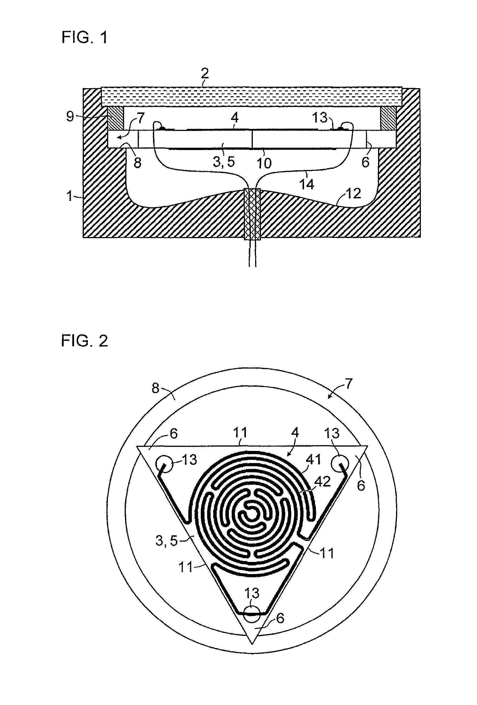
[0025]FIG. 1 shows a cross section of an infrared radiator arrangement with a radiator housing 1, the interior of which is closed off by an infrared-transmissive window 2. Arranged in the radiator housing 1 is a plate-shaped ceramic body 3, where a structured heat resistant layer 4 is shown applied on the side of the plate-shaped ceramic body 3 facing the window.

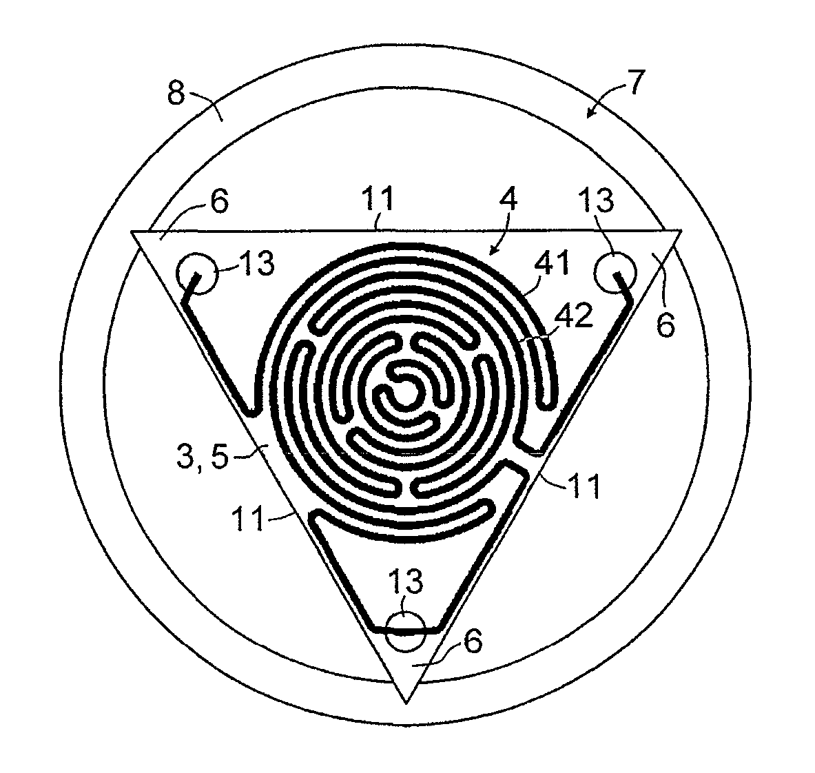
[0026]FIG. 2 shows a plan view of the plate-shaped ceramic body 3 comprising an equilateral triangular plate 5 mounted at its triangular tips 6 in a circumferential groove 7 arranged in the inner circumference of the radiator housing 1. The groove 7 is formed by a circumferential shoulder 8, situated in the radiator housing 1, and a clamping collar 9 arranged between the window 2 and the ceramic body 3. A heat resistant layer 4 consists of a platinum paste, which is applied to the ceramic body 3 by screen printing and subsequently baked. It is possible to print a plurality of heating structures 41, 42 or structures for tempe...


PUM


Abstract

A method and device for measuring the soot load in the exhaust gas systems of diesel engines using a sensor which is mounted downstream of a particulate filter and comprises a sensor element, to measure the operability of the particulate filter. According to the method, the soot load of the sensor element is measured resistively or capacitively using electrodes. The measuring voltage of the sensor element is controlled depending on at least one actual operating parameter of the diesel engine.

Description

CROSS-REFERENCE TO RELATED APPLICATIONS[0001]This is a U.S. national stage of International Application No. PCT / EP2010 / 053237, filed on 13 Mar. 2010. This patent application claims the priority of German Patent Application No. 10 2009 013 096.9, filed 13 Mar. 2009, the content of which is incorporated herein by reference its entirety.BACKGROUND OF THE INVENTION[0002]1. Field of the Invention[0003]The invention relates to an infrared radiator arrangement for a gas analysis device including a radiator housing, a plate-shaped ceramic body arranged in the interior of the radiator housing and a structured heat resistant layer applied on the plate-shaped ceramic body housing and, where the interior of the radiation housing is closed off on one side by a radiation-transmissive window.[0004]2. Description of the Related Art[0005]Resistance radiators are usually used as broadband radiation source for infrared gas analysis, where a coiled filament is arranged in a reflector housing that is cl...

Claims


Application Information

Patent Timeline
Patent Type & Authority Patents(United States)
IPC IPC(8): A61N5/06H05B3/20H05G2/00G01J3/10
CPCG01J3/108G01K7/183G01N21/3504H01K1/18H01K7/00H05B3/141H05B3/265G01K2217/00G01N2201/06186H05B2203/032
Inventor BITTER, RALFHEFFELS, CAMIELHORNER, THOMAS
Owner SIEMENS AG
Why Eureka
Try Eureka