
Circuit For The Sinusodial Regulation Of The Electrical Power Supplied To A Load

Inactive Publication Date: 2007-12-27
PATARCHI ALBERTO
View PDF5 Cites 0 Cited by
  • Summary
  • Abstract
  • Description
  • Claims
  • Application Information

AI Technical Summary

Benefits of technology

[0010] Another object of the invention is to provide a circuit able to operate correctly without generating mechanical vibrations due to the sudden variations in the current supplied to the load.
[0011] A further object of the invention is to make available a circuit that minimises heat dissipation by the Joule effect.

Problems solved by technology

However, the regulating system briefly described above has a significant drawback, due to the generation of harmonics, especially of the third order, which cause considerable interference.
Although this second type of control generates less harmonic interference than the one described above, it is nonetheless not free of operative drawbacks; at least one filter is required to eliminate the switching frequency and, more in general, anti-interference filters are necessary to ensure that the regulating devices thus obtained comply with current standards.
Moreover, switching systems are characterised by undesired vibrations, which cause particularly annoying noises and resonance; these vibrations are due to the so-called “torque ripples”, caused by the sudden variations in the current supplied to the load.

Method used


Image

  • Circuit For The Sinusodial Regulation Of The Electrical Power Supplied To A Load
  • Circuit For The Sinusodial Regulation Of The Electrical Power Supplied To A Load
  • Circuit For The Sinusodial Regulation Of The Electrical Power Supplied To A Load

Examples


Embodiment Construction

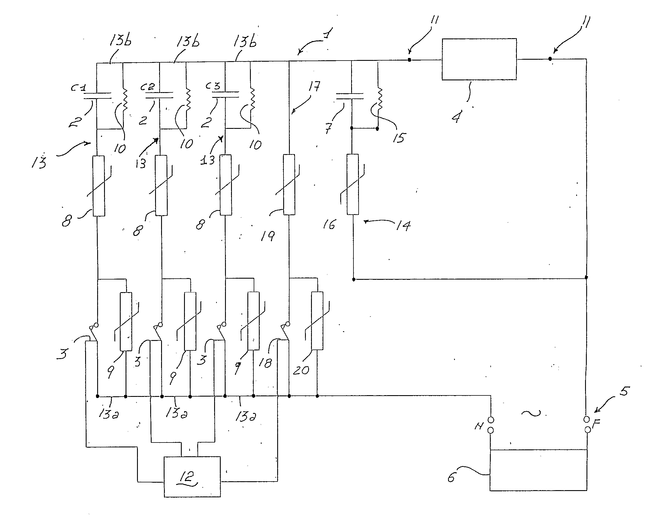
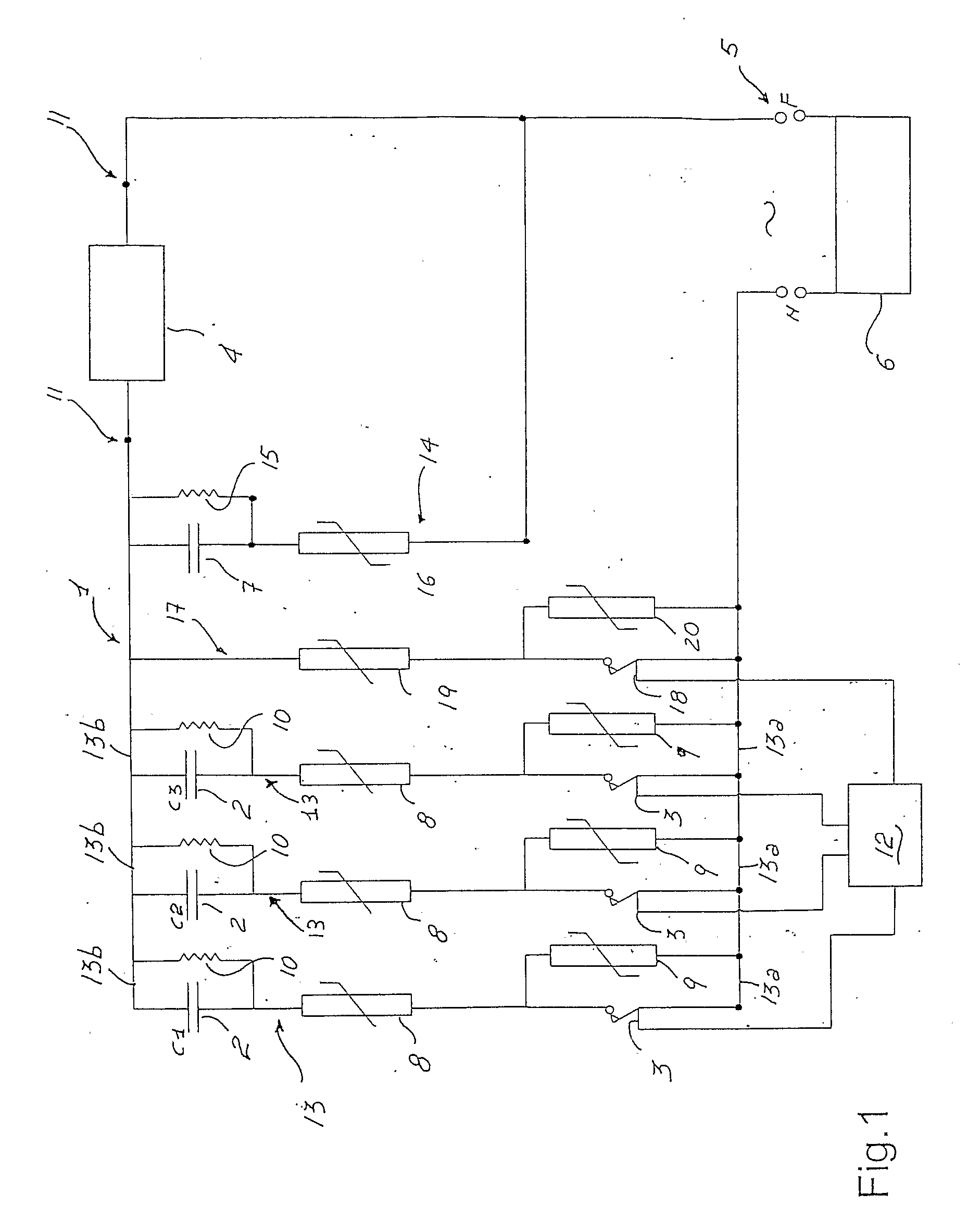
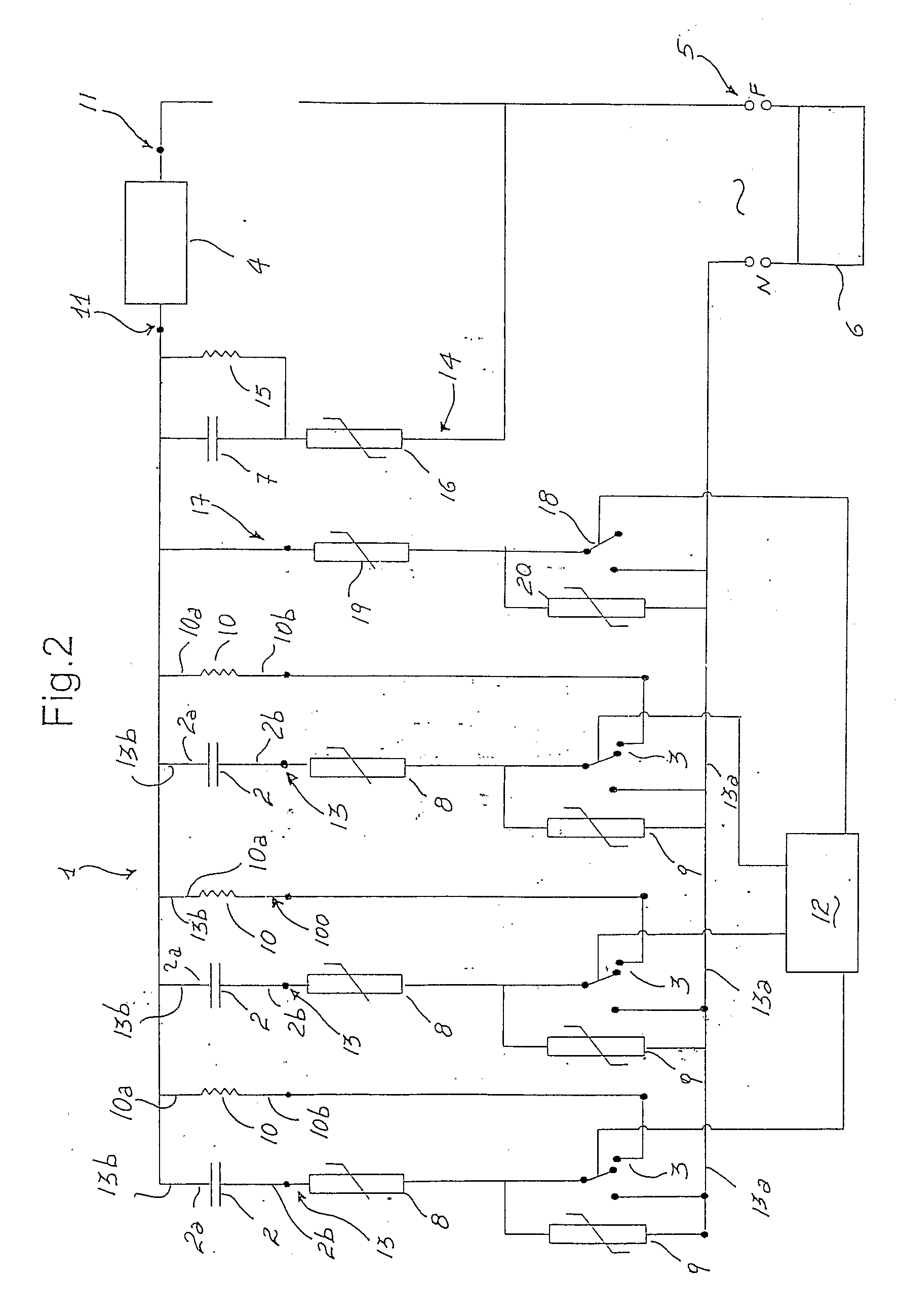
[0019] With reference to the accompanying drawings, the number 1 globally designates the circuit for the discrete regulation of the electrical power supplied to a load according to the invention.

[0020] The circuit 1 (FIGS. 1 and 2) comprises first of all an input interface 5, for connection to a unit or grid alternating power supply 6, and an output interface 11, for connection with a load 4.

[0021] The power supply unit 6, which can be constituted by a power supply grid or by any apparatus able to supply or generate electrical energy, makes a predetermined voltage available; purely by way of example, an electrical grid with alternating voltage (e.g. 220V) is considered herein, which is connected to the circuit 1 through the Neutral (N) and Phase (F) terminals.

[0022] In practice, the interface 5 can be constituted by any connecting means between the circuit 1 and the aforesaid power supply unit 6.

[0023] The output interface 11 instead defines the means used for the connection bet...


PUM


Abstract

A circuit for the sinusoidal regulation of the electrical power supplied to a load includes an input interface to receive an electrical power supply from a power supply unit and an output interface to supply a predetermined electrical power to a load; the circuit further includes a plurality of capacitive elements, a plurality of thermistor regulator elements and a plurality of commutators, each associated to a respective capacitive element. Each commutator is able to be driven between a first operative condition in which it closes a connection between the load, the respective capacitive element and the power supply unit, and a second operative condition in which it does not close such connection; a control block drives the commutators between their first and second operative condition and thus regulates the power supplied to the load, defining the capacitive reactance interposed between the power supply unit and the load.

Description

TECHNICAL FIELD [0001] The present invention relates to a circuit for the sinusoidal regulation of the electrical power supplied to a load. BACKGROUND ART [0002] As is well known, there are several types of regulation and control of the power supplied to resistive and inductive loads powered with alternating voltage. [0003] For example, both for lighting systems, and for electric motors, according to a first technique, through an appropriate commutator, the half-waves of the power current flow are throttled, thereby selecting the fraction of the total power that is allowed to reach the load. [0004] In other words, by controlling the conduction angle of the commutator it is possible to let only a part of power supply sinusoidal wave, thereby obtaining the desired power. [0005] However, the regulating system briefly described above has a significant drawback, due to the generation of harmonics, especially of the third order, which cause considerable interference. [0006] Therefore, ano...

Claims


Application Information

Patent Timeline
IPC IPC(8): H05B39/04
CPCH02M5/08
Inventor PATARCHI, ALBERTO
Owner PATARCHI ALBERTO
Learn More