Self-balancing photovoltaic energy storage system and method

a photovoltaic energy storage and self-balancing technology, applied in the field of photovoltaic energy storage systems, can solve problems such as the assembly of high-voltage battery packs, and achieve the effects of simple cost reduction, reduced power electronics needed, and reduced cos

Active Publication Date: 2021-04-20
PENN STATE RES FOUND
View PDF5 Cites 1 Cited by
  • Summary
  • Abstract
  • Description
  • Claims
  • Application Information

AI Technical Summary

Benefits of technology

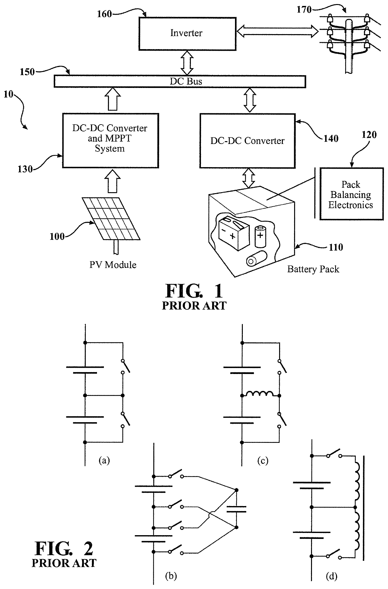
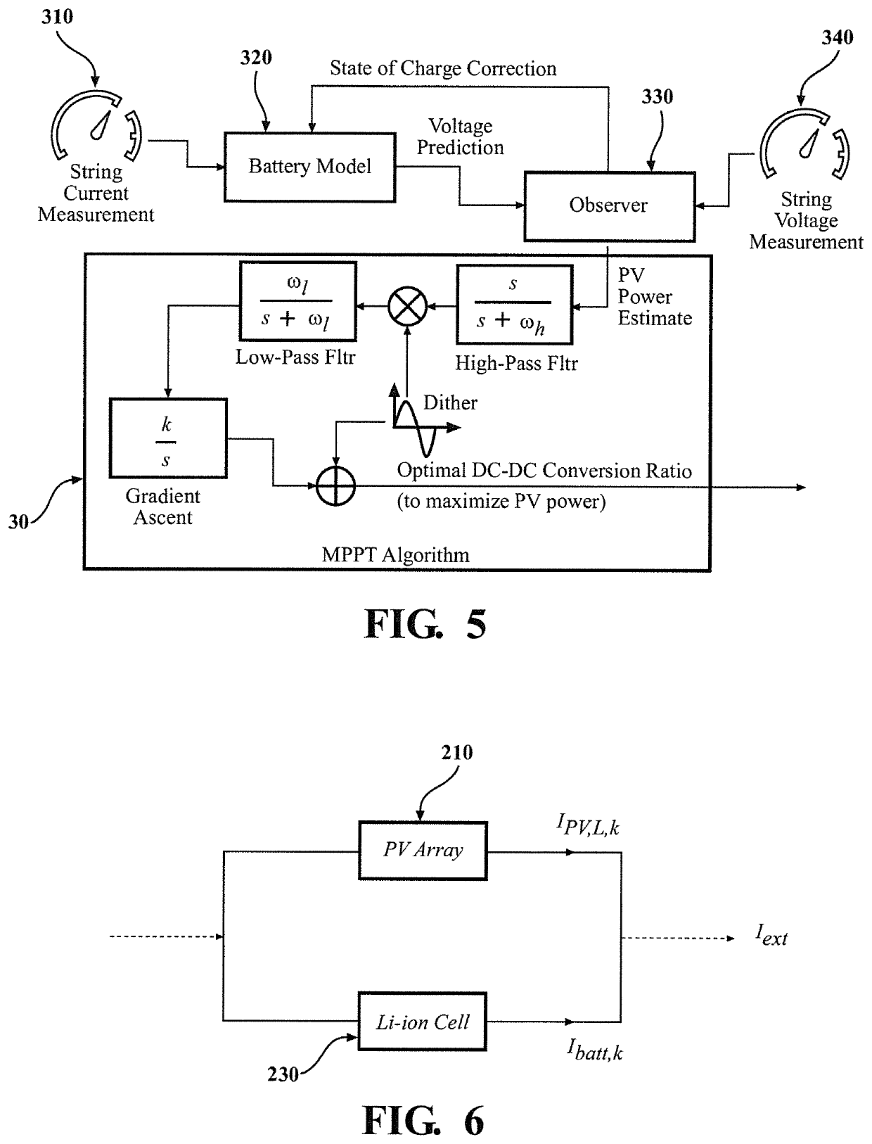
[0016]Certain embodiments of the present invention may reduce the cost of the power electronics needed for this integration by approximately 30 percent. The present invention enables existing PV systems to: (i) accommodate generation intermittencies and (ii) provide ancillary services to the grid such as frequency regulation and energy arbitrage at a relatively lower cost. The present invention's benefits will go beyond simple reductions in cost. Certain embodiments of this invention enable photovoltaic maximum-power-point tracking (MPPT) at a high level of granularity, thereby optimizing overall PV generation. In contrast to the prior art, certain embodiments of the present invention furnish a battery pack with a self-balancing capability, and with a self-balancing time constant that is completely independent of the battery pack size. This enables high-voltage battery pack operation (at voltages in the 2 kV-3 kV range), thereby minimizing heat dissipation in the combined PV-storage system. The battery pack for use with certain embodiments of the present invention may be a single battery cell or a combination of battery cells connected in parallel and / or series. Assembly of high voltage battery packs is an issue in the prior art since the time to eliminate cell imbalances by balancing power electronics is dependent on the string length and increases with increasing string length for some balancing architectures. In particular, certain embodiments of the present invention improve the overall efficiency of combined PV / storage systems and reduce the cost of these systems.
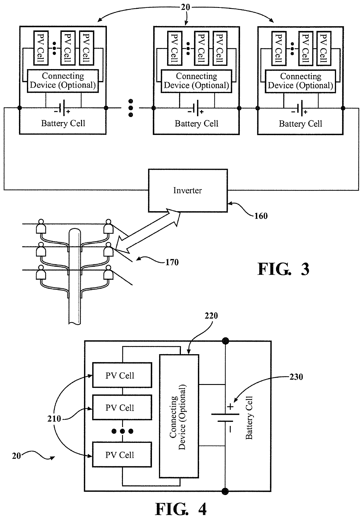
[0022]The present invention also discloses a method that includes the steps of (a) providing a plurality of hybrid cells, wherein each hybrid cell includes at least one solar power generating unit and an energy storage device; (b) generating a DC electrical power by the solar power generating units; (c) connecting the at least one solar power generating unit and the power storage device of each hybrid cell in parallel; (d) transferring the DC electrical power from the at least one solar power generating unit to the power storage cell; and (e) connecting the energy storage devices of the plurality of hybrid cells in series. The DC electrical power derived from the series of these power storage devices may energize a DC power load. The PV energy storage system may have an inverter operable to convert the DC electrical power into AC electrical power and the inverter is electrically coupled to the series of the power storage devices. The method may have a step of connecting at least one inverter to the series of power storage devices and transferring the DC electrical power from the power storage devices to the at least one inverter. The PV energy storage system is thus used for energizing an AC power load.

Problems solved by technology

Assembly of high voltage battery packs is an issue in the prior art since the time to eliminate cell imbalances by balancing power electronics is dependent on the string length and increases with increasing string length for some balancing architectures.

Method used


Image

  • Self-balancing photovoltaic energy storage system and method
  • Self-balancing photovoltaic energy storage system and method
  • Self-balancing photovoltaic energy storage system and method

Examples


Embodiment Construction

[0051]A self-balancing photovoltaic energy storage system and method according to the present invention may take a variety of forms. Various examples of the present invention are shown in the Figures. However, the present invention is not limited to the illustrated embodiments. Reference will now be made in detail to some embodiments of the present invention, examples of which are illustrated in the accompanying figures. Wherever possible, the same reference numbers will be used throughout the drawings to refer to the same or like parts. Additional objects and features of the invention will be set forth in part in the description that follows and in part will become apparent to those having ordinary skill in the art upon examination of the following or may be learned from practice of the invention. The objectives of the invention may be realized and attained by the structure particularly pointed out in the written description and claims hereof as well as the appended figures.

[0052]T...


PUM

PropertyMeasurementUnit
Open-circuit Voltageaaaaaaaaaa

Abstract

A photovoltaic (PV) energy storage system having a plurality of hybrid cells operable to generate DC electrical power. Each hybrid cell includes at least one solar power generation unit and a power storage device connected in parallel. The power storage devices of the plurality of hybrid cells are connected in series and the DC electrical power derived from the series of these power storage devices energizes a DC power load. The PV energy storage system has an inverter operable to convert DC electrical power into AC electrical power and is electrically coupled to the series of the power storage devices. The PV energy storage system energizes an AC power load, such as a power grid.

Description

REFERENCE TO RELATED APPLICATION[0001]This application claims priority to U.S. Provisional Patent Application Ser. No. 62 / 344,587, filed Jun. 2, 2016, the entire content of which is incorporated herein by reference.FIELD OF THE INVENTION[0002]The present invention relates to photovoltaic (PV) systems, and more specifically to the storage, management, optimization, and conversion of the electric energy they generate from DC to AC.BACKGROUND OF THE INVENTION[0003]During the past decade, there has been a rapid growth in the field of photovoltaic electricity generation. In the United States (US) alone, PV generation capacity is expected to grow to 135 GWe by 2030 compared to only 7 GWe in 2012. This growth creates a key challenge: once intermittent renewable resources such as solar and wind energy exceed 20-25% market penetration, balancing instantaneous electricity supply and demand will become difficult for the traditional power grid. Therefore, technologies such as demand response an...

Claims


Application Information

Patent Timeline
Patent Type & Authority Patents(United States)
IPC IPC(8): H02J3/38H02S40/38H02J7/35G05F1/67H01M10/46H01M10/44H02J1/10H01M10/48H02S40/32H02J7/00H01M10/42H01M10/052
CPCH02J3/385G05F1/67H01M10/441H01M10/46H01M10/482H02J1/102H02J7/0014H02J7/35H02S40/32H02S40/38H01M10/052H01M2010/4271Y02E10/56H02J2300/26H02J3/381Y02E60/10Y02E70/30H02J3/38
Inventor FATHY, HOSAM K.
Owner PENN STATE RES FOUND
Why Eureka
Try Eureka