
Noise detection method, noise detection apparatus, simulation method, simulation apparatus, and communication system

a noise detection and noise detection technology, applied in the field of communication systems, can solve the problems of event-driven timing of the operation of the actuator serving as a source of generation of impulsive noise, affecting the section of an impulsive noise to be detected, and never realizing noise detection, etc., to achieve favorable communication, high accuracy, and high accuracy

Inactive Publication Date: 2013-10-01
AUTONETWORKS TECH LTD +2
View PDF20 Cites 4 Cited by
  • Summary
  • Abstract
  • Description
  • Claims
  • Application Information

AI Technical Summary

Benefits of technology

The present invention provides a method and apparatus for detecting noise in a communication medium. The invention aims to remove subjective detection conditions as much as possible and accurately detecting impulsive noise from the statistical property of the observed noise. This allows for the simulation of impulsive noise during the design of the communication system, leading to the selection of an optimal frequency for avoiding impulsive noises. The invention can also be used to select communication parameters based on the frequency. Technical effects include improved accuracy in detecting impulsive noise and designing communication systems that effectively avoid impulsive noises.

Problems solved by technology

Thus, there is a disadvantage that a section of an impulsive noise to be detected is influenced by the foregoing impulsive noise detection condition.
Accordingly, even if noise detection from which human subjectivity is removed is desired, such noise detection has never been realized.
The timing of operation of the actuator serving as a source of generation of an impulsive noise is event-driven.
However, an event-driven operation, i.e., an actuator operation such as locking / unlocking of an electric door lock of a vehicle, is carried out in response to an operation corresponding to turning ON / OFF of a switch by a driver or a fellow passenger, and an impulsive noise is generated from a door lock actuator or the like in response to turning ON / OFF of the switch of the door lock, thus making it impossible to learn the foregoing temporal characteristics.

Method used


Image

  • Noise detection method, noise detection apparatus, simulation method, simulation apparatus, and communication system
  • Noise detection method, noise detection apparatus, simulation method, simulation apparatus, and communication system
  • Noise detection method, noise detection apparatus, simulation method, simulation apparatus, and communication system

Examples


embodiment 1

[0152]FIG. 6 is a block diagram illustrating a configuration of an in-vehicle PLC system according to Embodiment 1. The in-Vehicle PLC system includes: a plurality of ECUs 1, 1, . . . ; actuators 2, 2, . . . operated in response to control data transmitted from the ECUs 1, 1, . . . ; power lines 3, 3, . . . through which electric power is supplied to each of the ECUs 1, 1, . . . and the actuators 2, 2, . . . ; a battery 4 for supplying electric power to respective devices through the power lines 3, 3, . . . ; a junction box 5 for branching and junction of the power lines 3, 3, . . . ; and a noise detection apparatus 6 for detecting a noise in each power line 3.

[0153]As illustrated in FIG. 6, in Embodiment 1, the ECUs 1, 1, . . . and the actuators 2, 2, . . . make bus-type connections to the power line 3. A connection topology may be a star-type connection, or may be a combined type in which a bus-type connection and a star-type connection are combined.

[0154]The battery 4 is charged ...

embodiment 2

[0202]In Embodiment 2, a Determination is Further Made Using statistical information in the process of impulsive noise detection processing performed by the noise detection apparatus 6 described in Embodiment 1. In other words, measurement data including only a Gaussian noise is not subjected to an estimation process that uses a BW algorithm and MAP estimation. Thus; the detection accuracy can be increased.

[0203]Configurations of an in-vehicle PLC system and a noise detection apparatus 6 according to Embodiment 2 are similar to those of the in-vehicle PLC system and noise detection apparatus 6 according to Embodiment 1, and Embodiment 2 differs from Embodiment 1 only in details of the processing executed by the noise detection apparatus 6. Accordingly, in the following description, constituent elements common to those of Embodiment 1 are identified by the same reference characters, and detailed description thereof will be omitted.

[0204]FIG. 16 is a functional block diagram illustrat...

embodiment 3

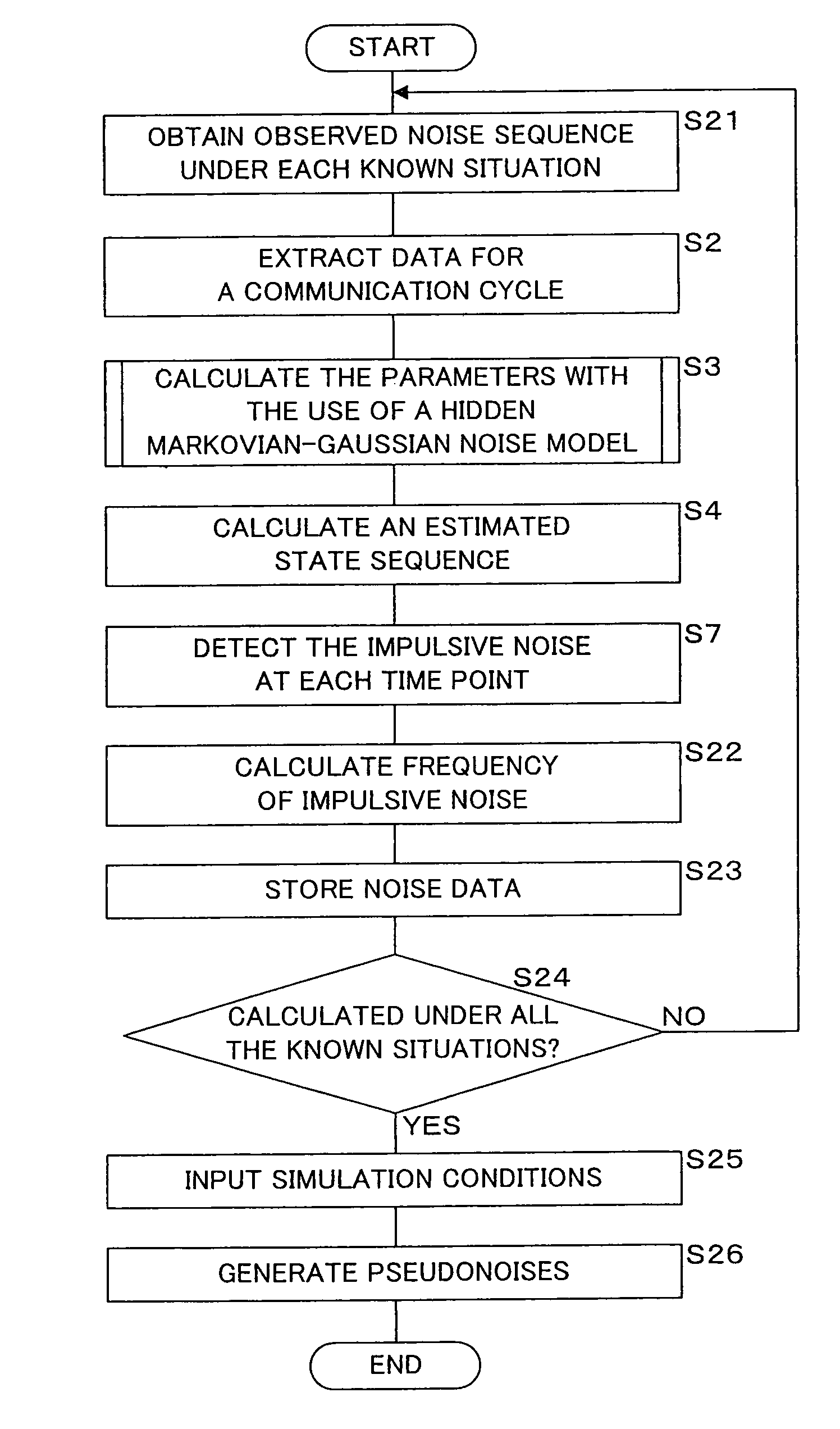
[0261]In Embodiment 3, Observed Noise Sequences are Obtained under known situations, results of calculation of state sequences and noise characteristics performed by the noise detection apparatus 6 according to Embodiment 1 or 2 are obtained, impulsive noise frequencies detected using the calculation results are calculated, the calculation results and impulsive noise frequencies are stored in association with the respective situations, and then a simulation is carried out using the noise characteristics and impulsive noise frequencies.

[0262]FIG. 24 is a block diagram illustrating a configuration of a simulation apparatus according to Embodiment 3. Using a personal computer, the simulation apparatus 7 includes: a control section 70; a storage section 71; a temporary storage section 74; a condition input section 75; and a pseudonoise generation section 76. Using a CPU, the control section 70 executes a simulation based on a simulation program 72 stored in the storage section 71. Using...


PUM


Abstract

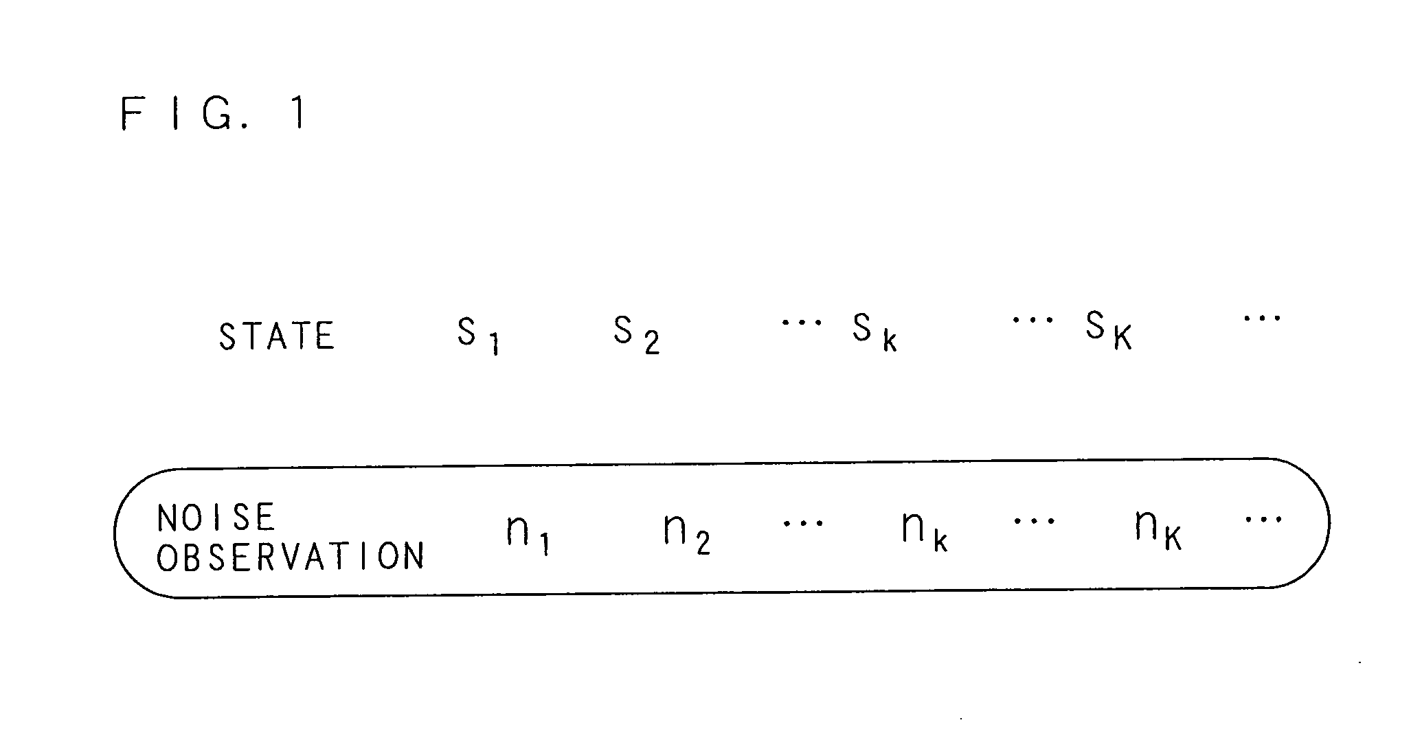
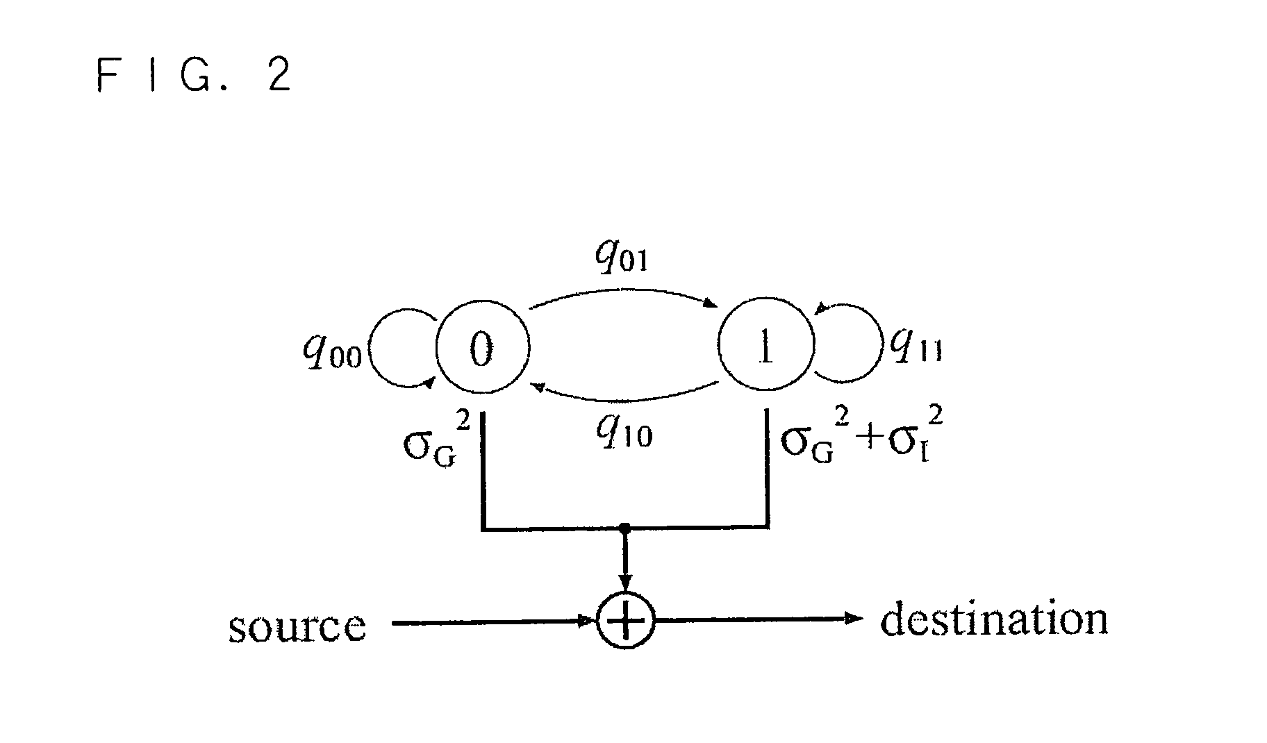
For voltage values (observed noise sequence) in an electronic power line (communication medium) which are obtained at a predetermined interval, initial values of noise characteristics based on a statistic of the observed noise sequence itself are decided by a moment method (S301 to S307), the noise characteristics (state transition probabilities and state noise power) for maximization of the likelihood of the observed noise sequence are obtained from the initial values by MAP (Maximum A Posteriori) estimation using a Baum-Welch algorithm (S309 to S312), a state sequence is estimated from the obtained noise characteristics, and an impulsive noise at each time point is detected.

Description

CROSS-REFERENCE TO RELATED APPLICATIONS[0001]This Nonprovisional application claims priority under 35 U.S.C. §119(a) on Patent Application No. 2009-150251 filed in Japan on Jun. 24, 2009, No. 2009-266707 filed in Japan on Nov. 24, 2009 and No. 2010-131191 filed in Japan on Jun. 8, 2010, the entire contents of which are hereby incorporated by reference.BACKGROUND OF THE INVENTION[0002]1. Field of the Invention[0003]The present invention relates to a communication system including a plurality of communication apparatuses. In particular, the present invention relates to a noise detection method, a noise detection apparatus, a simulation method, a simulation apparatus and a communication system which are capable of automatically detecting an impulsive noise, generated suddenly in a communication medium, from a statistical property of the observed noise itself.[0004]2. Description of Related Art[0005]Recently, in each field, there has been utilized a system in which a plurality of commun...

Claims


Application Information

Patent Timeline
Patent Type & Authority Patents(United States)
IPC IPC(8): H04B3/46H04Q1/20H04B17/00
CPCG06N7/02H04B17/345H04B17/0055H04B3/54
Inventor UMEHARA, DAISUKEMORIKURA, MASAHIROHISADA, TOSHIYAISHIKO, SHINICHIHORIHATA, SATOSHI
Owner AUTONETWORKS TECH LTD
Learn More