
Apparatus and method for checking thickness dimensions of an element while it is being machined

a technology of thickness measurement and machine, which is applied in the direction of semiconductor/solid-state device testing/measurement, optical radiation measurement, instruments, etc., can solve the problems of dimensional values, inability to apply in the event of need, and limit of these systems, so as to prevent air bubble formation, high performance standards, and regular flow of fluid

Active Publication Date: 2013-10-01
MARPOSS SPA
View PDF31 Cites 0 Cited by
  • Summary
  • Abstract
  • Description
  • Claims
  • Application Information

AI Technical Summary

Benefits of technology

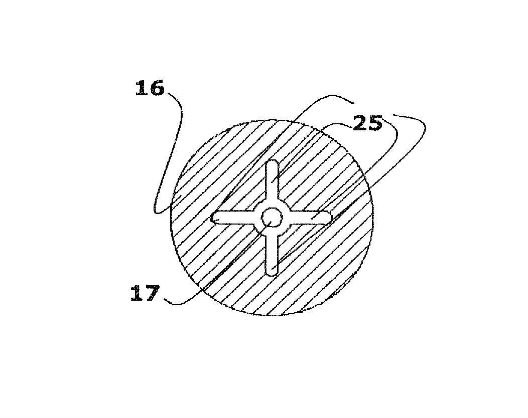
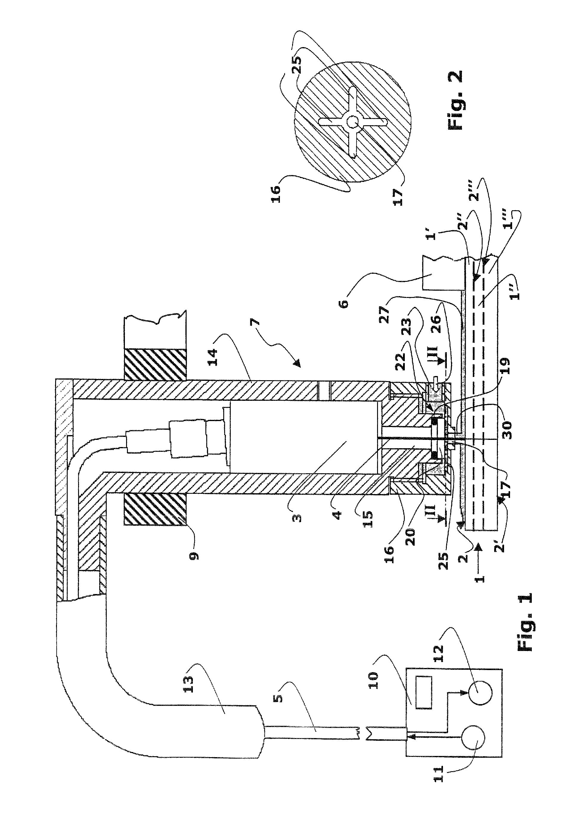
The present invention provides an apparatus and method for checking the thickness of semiconductor wafers during grinding operations that is reliable, flexible, and performs at a high standard. The apparatus includes an optical probe and a support and positioning element for the probe. A low flow fluid is piped at a limited area to create a clean surface layer without causing turbulences. The probe is positioned in relation to the machined surface of the piece in such a way that the light beam passes through the air and the fluid layer before reaching the surface. The apparatus also includes radial channels in the support and positioning element which are tangent to the separating glass to prevent air bubbles and improve the flow of the fluid. This invention solves the problems of current measuring methods.

Problems solved by technology

Systems of this kind, which may affect the checked piece and do not allow to fall below certain dimensional values, cannot be applied in the event there is needed, as frequently occurs, to accurately check the thickness of a semiconductor wafer having one side fixed to a film or a support element.
However, the limits of these systems concern both the dimension that can be checked (for example a thickness of less than 100 micron cannot be checked) and the achievable resolution (not less than 10 micron).
In this way the operation of the optical probe may be affected, in particular owing to unwanted and uncontrollable alterations of the characteristics of the transmitted and / or received beams that are due to the discontinuities of the transmission element and / or to turbulence phenomena in the cleaning fluid.
Moreover, the different media generate a partial absorption of the radiation and thus limit the luminous intensity given back to the probe.
As a consequence, it is necessary to employ higher electrical amplifications, and the probe becomes more exposed to background noises.
In the event cleaning air is employed, this latter must be carefully filtered for avoiding to introduce foreign material which would interfere with the checking and would contaminate the surface, causing a consequent increasing of costs.
Moreover, the mechanical effect of the air jet on the piece being machined, in particular on very small silicon thicknesses (until 5-10 micron) is not negligible.

Method used


Image

  • Apparatus and method for checking thickness dimensions of an element while it is being machined
  • Apparatus and method for checking thickness dimensions of an element while it is being machined

Examples


Embodiment Construction

[0013]FIG. 1 shows an apparatus for checking thickness dimensions of an element in a working condition. The checked element is for example a slice or wafer 1, of semiconductor material such as silicon, that may be formed of layers 1′, 1″, 1′″, with different physical features, separated by discontinuity surfaces 2″, 2′″. The structure of the wafer with layers and discontinuity surfaces is per se well known and is shown in a very schematic way in FIG. 1. The number and dimensions of layers is also shown just as an example. The thickness checking can be carried out while a first surface 2 of the wafer 1 is grinded on an appropriate machine tool, which is per se known and, for the sake of simplicity, is indicated in FIG. 1 with the reference number 6 showing a grinding wheel in a simplified way.

[0014]A detection system includes an optical probe 3 of a known type connected to a control and processing unit 10 by means of an optical fibre 5, a source 11 emitting light in the infrared band...


PUM

PropertyMeasurementUnit
anglesaaaaaaaaaa
thicknessaaaaaaaaaa
thicknessaaaaaaaaaa

Abstract

An apparatus for checking thickness dimensions in a semiconductor wafer (1) during grinding operations includes an optical probe (3) which transmits infrared radiations on the surface (2) being machined of the wafer (1), and detects beams that are reflected by said surface, by an opposite surface (2′) of the wafer and / or by surfaces (2″, 2′″) separating different layers in the wafer. The beam of emitted and reflected radiations travels along a path (4) with known and constant discontinuities, in part through the air (15) and in part through a cushion (30) of low flow liquid, which flows with substantially laminar flow. A support and positioning element (7) for the optical probe includes hydraulic ducts (22,25) that generate the liquid cushion. A method for checking the thickness dimensions includes the generation of the liquid cushion at the path along which the beam of emitted and reflected radiations travels.

Description

TECHNICAL FIELD[0001]The present invention relates to an apparatus for checking thickness dimensions of semiconductor wafers during the machining on a grinding machine, including a detection system with a light source in the infrared band, a detector of reflected beams, and an optical probe, the light source and the detector being connected to the optical probe for emitting infrared beams along a longitudinal path towards a first surface of the wafer being machined, and for receiving, substantially along the longitudinal path, beams reflected by the first surface and by at least one different surface defined by the wafer being machined, a support and positioning element for the optical probe, and a control and processing unit connected to the detection system.[0002]The present invention also relates to a method for checking thickness dimensions of semiconductor wafers during the machining on a grinding machine by means of an infrared optical probe and an associated support and posit...

Claims


Application Information

Patent Timeline
Patent Type & Authority Patents(United States)
IPC IPC(8): G01N21/35G01B11/06
CPCB24B7/228B24B49/12G01B11/06H01L22/26
Inventor DALL'AGLIO, CARLO
Owner MARPOSS SPA
Learn More