Liquid ejection head and manufacturing method thereof

a technology of liquid ejection and manufacturing method, which is applied in the direction of metal-working apparatus, printing, writing implements, etc., can solve the problems of blurred printed images, affecting the normal ejection of liquid, so as to prevent clogging of filters, stable liquid ejection, and reduce liquid flow. effect of ra

Inactive Publication Date: 2013-10-01
CANON KK
View PDF8 Cites 1 Cited by
  • Summary
  • Abstract
  • Description
  • Claims
  • Application Information

AI Technical Summary

Benefits of technology

[0009]Therefore, it is an object of the present invention to provide a liquid ejection head capable of preventing clogging of a filter when dust and foreign matters in liquid are collected, thereby performing stable ejection of liquid without decreasing the liquid flow rate even after collecting dust, and also provide a manufacturing method of the liquid ejection head.

Problems solved by technology

However, as the diameter of the ink ejection orifice becomes smaller for addressing a further degree of micro-fabrication, the ink ejection orifice, which is fabricated more minutely, may be clogged with dust in ink, thereby hindering normal ejection.
However, the conventional filter structure collects dust in ink on the surface of the filter, and hence dust is apt to reach the through holes of the filter.
As a result, blurs and unevenness of printed images may be caused.

Method used


Image

  • Liquid ejection head and manufacturing method thereof
  • Liquid ejection head and manufacturing method thereof
  • Liquid ejection head and manufacturing method thereof

Examples


example 1

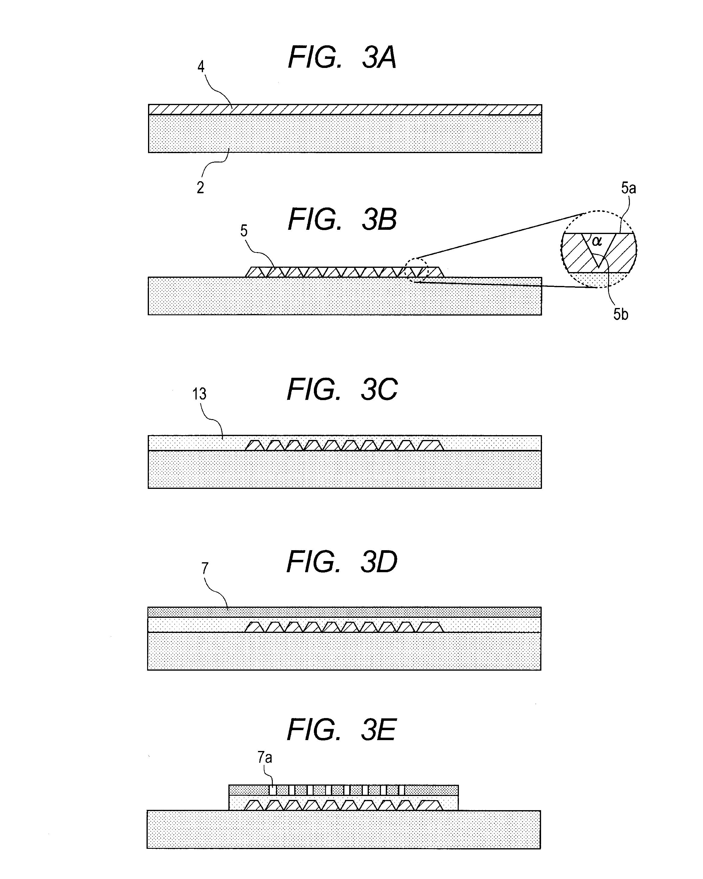
[0064]Hereinafter, an example of the present invention is described with reference to FIGS. 3A to 4E.

[0065]First, as illustrated in FIG. 3A, a silicon wafer having a diameter of 150 mm and a thickness of 625 μm on which heater elements and driving circuits had been formed was prepared as a heater board (substrate 2).

[0066]On this heater board, a resin for forming the shapes of the tapered shape structures 3 was applied by spin-coating to form the resist layer 4. As the resin, a positive type resist produced by TOKYO OHKA KOGYO CO., LTD., OFPR-50 cp (trade name) was used. The number of revolutions of the spin coating was adjusted so that the film thickness of the resist layer 4 became 5 μm, provided that the baking temperature after applying the resin was 100° C. and the baking time was 10 minutes. After the application, the film thickness from the heater board 2 to the surface of the resist layer 4 was measured to be 5 μm.

[0067]This resist layer 4 was patterned by photolithography t...


PUM

PropertyMeasurementUnit
heightaaaaaaaaaa
tapering angleaaaaaaaaaa
heightaaaaaaaaaa

Abstract

Provided is a liquid ejection head, including: an ejection orifice forming member having an ejection orifice for ejecting liquid; a substrate having a supply port for supplying the liquid to the ejection orifice; and a filter disposed at a position upstream of the ejection orifice when the liquid is supplied to the ejection orifice, in which the filter includes an opening having a diameter smaller than or equal to a diameter of the ejection orifice, and a tapered shape structure disposed at a position upstream of the opening when the liquid is supplied to the ejection orifice, the tapered shape structure having a distal end directed toward an upstream side.

Description

BACKGROUND OF THE INVENTION[0001]1. Field of the Invention[0002]The present invention relates to a liquid ejection head and a manufacturing method thereof.[0003]2. Description of the Related Art[0004]As an example of a liquid ejection head for ejecting liquid, there is known an ink jet recording head used for an ink jet printing method in which small ink droplets are ejected and applied to a recording medium such as paper.[0005]With the advancement of the recording technologies in recent years, for the ink jet recording head, it is required that the density of array of ejection orifices for ejecting ink should be made higher, and the shapes of the ejection orifices and flow paths communicating thereto should be fabricated more minutely. Japanese Patent Application Laid-Open No. H06-286149 discloses a method of manufacturing a liquid ejection head in which a nozzle layer is formed on a silicon wafer, which has been provided in advance with heater elements and driving circuits, with a...

Claims


Application Information

Patent Timeline
Patent Type & Authority Patents(United States)
IPC IPC(8): B41J2/17
CPCB41J2/1603B41J2/1623B41J2/1626B41J2/1631B41J2/1639B41J2/1645B41J2002/14403Y10T29/49401
Inventor KUROSU, TOSHIAKISASAKI, KOJIHASEGAWA, KOUJIIBE, SATOSHITAGAWA, YOSHINORI
Owner CANON KK
Why Eureka
Try Eureka