Liquid ejection apparatus, cleaning apparatus for liquid ejection head, and inkjet recording apparatus

Inactive Publication Date: 2013-08-29
FUJIFILM CORP
View PDF3 Cites 6 Cited by
  • Summary
  • Abstract
  • Description
  • Claims
  • Application Information

AI Technical Summary

Benefits of technology

The present invention aims to improve the cleaning properties of liquid ejection heads in liquid ejection apparatuses, inkjet recording apparatuses, and cleaning apparatuses for liquid ejection heads. This is achieved by suppressing the slack of the long wiping member when it comes in contact with the liquid ejection face and causes it to wipe the face. The invention provides a liquid ejection apparatus including a long wiping member, a wiping member conveyance device, a pressing member, an elastic member, a relative movement device, and a slack eliminating member. The slack eliminating member is placed between the liquid ejection head and the long wiping member and helps to eliminate slack in the long wiping member to ensure a new cleaning surface for every wipe, thereby improving the wiping properties.

Problems solved by technology

When the foreign material adheres to the nozzles and / or the periphery thereof, the adhering material affects ink droplets ejected from the nozzles and causes deviation in the ejection direction of the ink droplets, and it is then difficult to deposit the ink droplets at prescribed positions on the recording medium.
As a result of this, the output image quality declines.
However, the apparatus according to Japanese Patent Application Publication No. 2005-022251 does not include any device to manage the pressing force.
However, due to the deformation of the elastic member, the sheet-formed flexible cleaning device (the wiping member such as cloth or film) is distorted, and it becomes impossible to convey the cleaning device.
When it becomes impossible to convey the cleaning device due to the occurrence of distortion, the wiping surface of the sheet-shaped cleaning device is not renewed, then the wiping surface having been soiled is used to wipe the head, and hence there is a problem in that the soiling becomes attached again to the nozzle face.
An issue of this kind is not limited to the inkjet printer, but rather is also a common problem in liquid ejection apparatuses of various kinds which use liquid ejection heads.

Method used


Image

  • Liquid ejection apparatus, cleaning apparatus for liquid ejection head, and inkjet recording apparatus
  • Liquid ejection apparatus, cleaning apparatus for liquid ejection head, and inkjet recording apparatus
  • Liquid ejection apparatus, cleaning apparatus for liquid ejection head, and inkjet recording apparatus

Examples


first embodiment

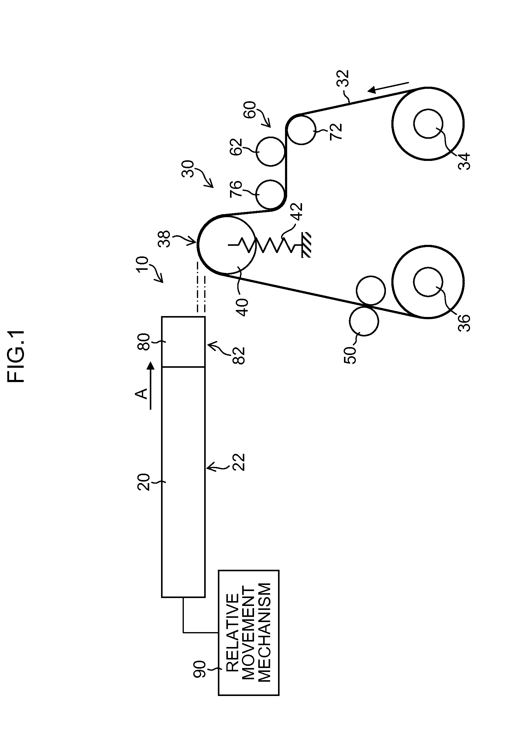
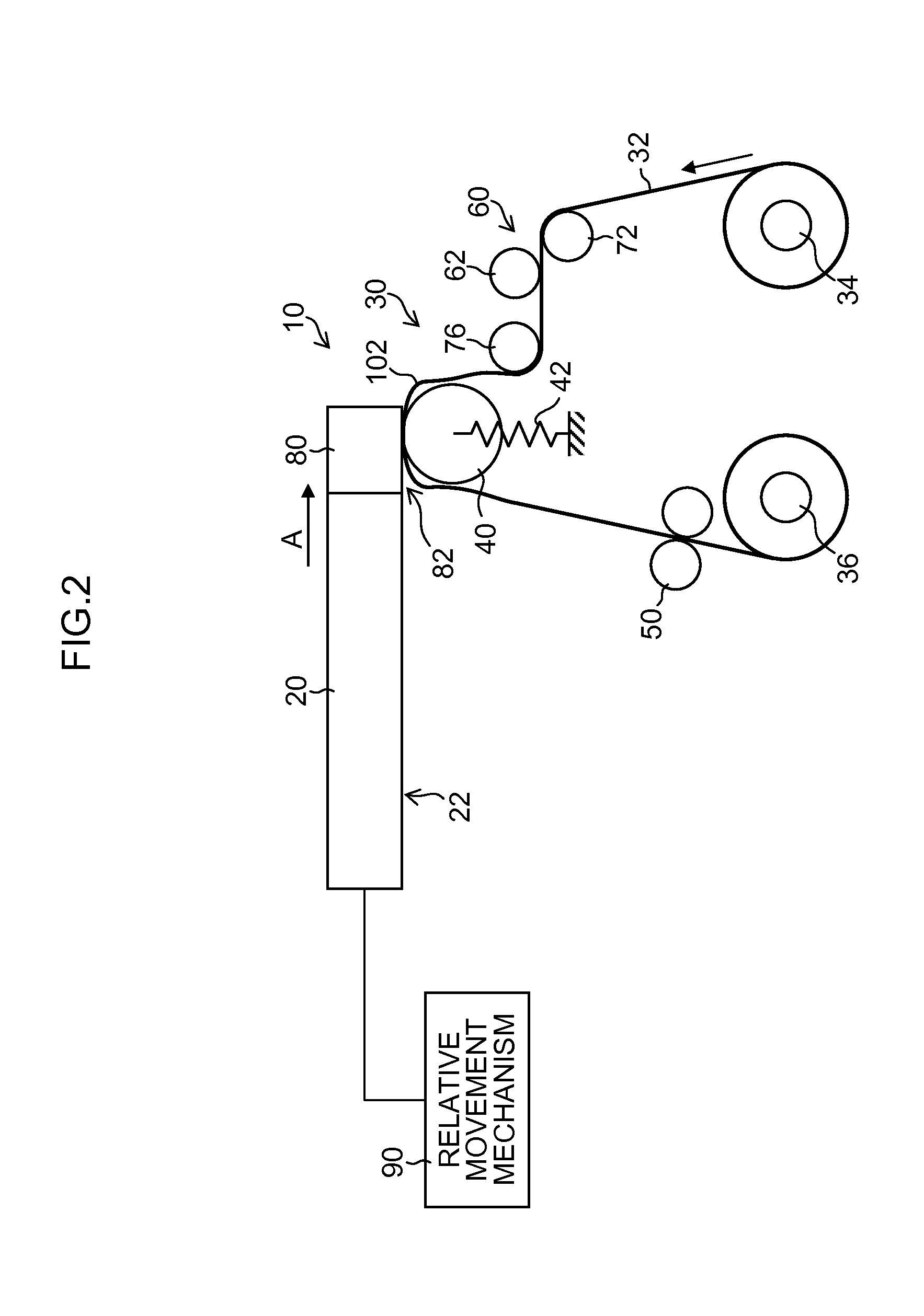
[0055]FIG. 1 is a schematic diagram showing a composition of a liquid ejection apparatus 10 according to a first embodiment of the present invention. As shown in FIG. 1, the liquid ejection apparatus 10 includes: a liquid ejection head (hereinafter referred to as the “head”) 20; a wiping unit 30, which wipes and cleans a nozzle face 22 (corresponding to a “liquid ejection face”) of the head 20; and a slack eliminating member 80, which is arranged on a lateral side of the head 20.

[0056]The wiping unit 30 includes: a pay-out side web core 34 (corresponding to a “first core”), which supplies a long wiping web 32 (corresponding to a “wiping member”); a take-up side web core 36 (corresponding to a “second core”), which takes up the wiping web 32 paid out from the pay-out side web core 34; a pressing roller 40 (corresponding to a “pressing member”), which is arranged in a web conveyance path from the pay-out side web core 34 to the take-up side web core 36 so that the wiping web 32 is wra...

second embodiment

[0086]FIG. 4 is a schematic drawing showing a composition of a liquid ejection apparatus 110 according to a second embodiment of the present invention. In FIG. 4, the elements which are the same as or similar to those in the first embodiment described with reference to FIGS. 1 to 3 are denoted with the same reference numerals, and description thereof is omitted here.

[0087]The liquid ejection apparatus 110 according to the second embodiment shown in FIG. 4 includes: a slack sensor 114 (corresponding to a “detection device”), which detects the slack 102 in the wiping web 32; and a control circuit 120 (corresponding to a “control device”), which controls driving of the web conveyance motor 116 according to a detection signal obtained from the slack sensor 114.

[0088]As a device for detecting the slack 102 of the wiping web 32, for example, it is possible to use a reflective type optical sensor, which irradiates the wiping web 32 with light from a light-emitting element, such as a laser ...

modification embodiment 1

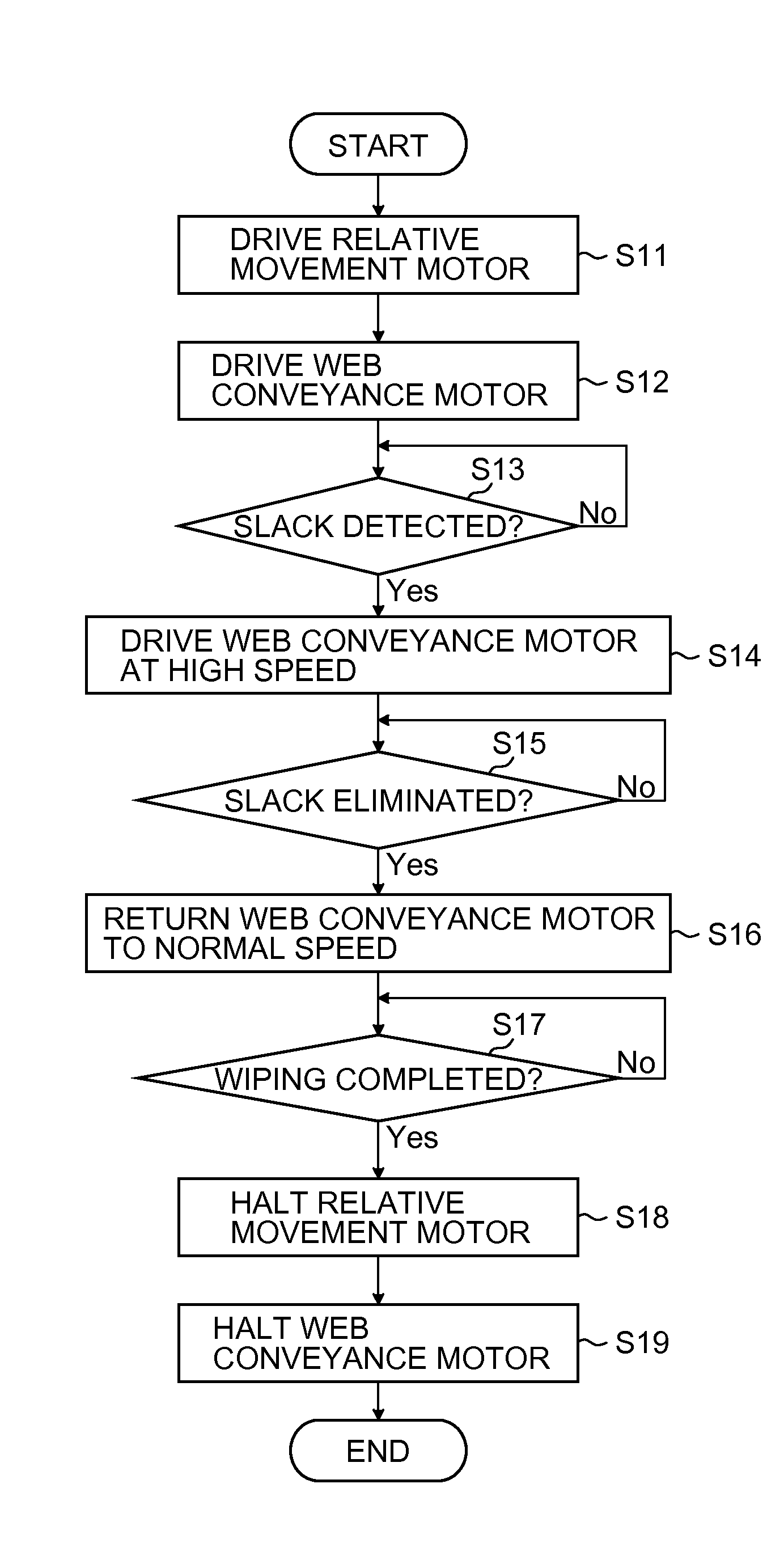
[0099]An alternative method to the second embodiment is one in which the slack sensor 114 is omitted and the web conveyance motor 116 is driven at high speed at the timing that the wiping web 32 comes in contact with the slack eliminating member 80. For example, it is possible to implement control by which the web conveyance motor 116 is driven at high speed from the time at which the wiping web 32 comes in contact with the slack eliminating member 80, and after a prescribed time period which is set previously as the time required to eliminate the slack has elapsed, the web conveyance motor 116 is returned to the normal speed (low-speed driving). In this case, in setting the prescribed time during which the high-speed driving is continued, the required time is investigated experimentally in accordance with various conditions, such as the web conveyance speed, the relative head speed, the amount of slack that occurs, and the like, and a suitable margin can be added.

[0100]According to...


PUM


Abstract

A liquid ejection apparatus includes: a liquid ejection head; a long wiping member configured to come in contact with and wipe a liquid ejection face of the head; a wiping member conveyance device configured to convey the wiping member in a lengthwise direction of the wiping member; an elastic member configured to elastically deform and apply a force to cause the wiping member to be pressed against the liquid ejection face through a pressing member when the wiping member comes in contact and pressed against the liquid ejection face; and a slack eliminating member arranged in a front side of the head in a direction of travel of the head with respect to the wiping member, the slack eliminating member being configured to eliminate slack in the wiping member caused by elastic deformation of the elastic member when the wiping member comes in contact with the slack eliminating member.

Description

BACKGROUND OF THE INVENTION[0001]1. Field of the Invention[0002]The present invention relates to a liquid ejection apparatus, a cleaning apparatus for a liquid ejection head, and an inkjet recording apparatus, and more particularly to head cleaning technology for wiping a liquid ejection face of a liquid ejection head by means of a long wiping member, and to a liquid ejection apparatus and an inkjet recording apparatus using this technology.[0003]2. Description of the Related Art[0004]In an inkjet recording apparatus, with use, foreign material such as ink residue or paper dust adheres to a liquid ejection face (a nozzle face formed with nozzles) of a liquid ejection head. When the foreign material adheres to the nozzles and / or the periphery thereof, the adhering material affects ink droplets ejected from the nozzles and causes deviation in the ejection direction of the ink droplets, and it is then difficult to deposit the ink droplets at prescribed positions on the recording medium...

Claims


Application Information

Patent Timeline
IPC IPC(8): B41J2/165
CPCB41J2/16535B41J2/2146B41J2/16579B41J2/165B41J2002/1655
Inventor INOUE, HIROSHI
Owner FUJIFILM CORP
Why Eureka
Try Eureka