
Multifunctional high strength metal composite materials

Active Publication Date: 2013-09-17
AMARANTHINE RESOURCES LLC
View PDF19 Cites 67 Cited by
  • Summary
  • Abstract
  • Description
  • Claims
  • Application Information

AI Technical Summary

Benefits of technology

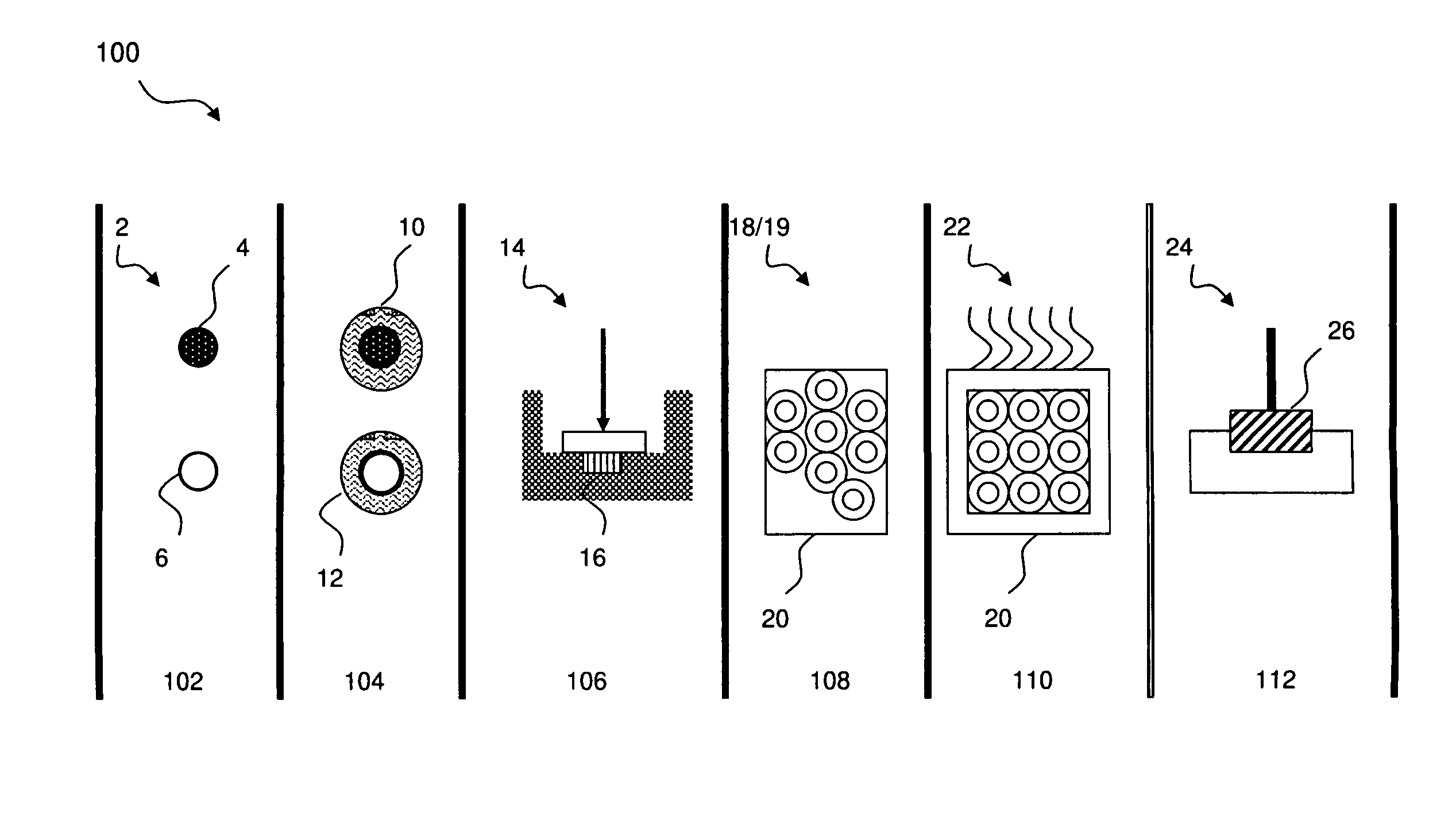
This patent describes a method to create strong metal composites with specific properties such as radiation hardening, X-ray shielding, and corrosion resistance. The method involves using micro-engineered particles mixed with a powder and shaped into a near net shape article. This article is then consolidated using heat and pressure in a solid state process to produce the metal matrix composite with the desired property. This invention allows for the creation of highly functional materials that exhibit controlled properties and improved surface finish.

Problems solved by technology

Consequently, prior art metal composites are light, but do not have the strength, durability or stiffness necessary to compete against materials such as beryllium or aluminum.
Closed cell foams are generally very weak, under 5-10 ksi tensile strength, have a poor surface finish, and are not easily machined.
Likewise, joining and attaching these composites have inherent technical problems including low quantity processing capability.
Prior art in shielding of metals has been limited to preventing low level electro-magnetic interference by a physical attachment of heavy metal cladding such as nickel, but not in preventing x-ray radiation, prompt nuclear dose, or neutron absorption by use of a micro-engineered composite having the capability inherent to the core composite.
High heat causes inter-facial reactions and associated detrimental effects due to oxidation of the molten matrix.
High heat / molten processing requires special handling in instances involving molten magnesium and aluminum due to their tendency to react violently in air, thereby also increasing the cost and risk associated with these methods.
During the process, large anisotropic strains are introduced which cause significant particle deformation.

Method used


Image

  • Multifunctional high strength metal composite materials
  • Multifunctional high strength metal composite materials
  • Multifunctional high strength metal composite materials

Examples


Embodiment Construction

[0023]The following detailed description illustrates the invention by way of example, not by way of limitation of the scope, equivalents or principles of the invention. This description will clearly enable one skilled in the art to make and use the invention, and describes several embodiments, adaptations, variations, alternatives and uses of the invention.

[0024]In this regard, the invention is illustrated in the several figures, and is of sufficient complexity that the many parts, interrelationships, and sub-combinations thereof simply cannot be fully illustrated in a single patent-type drawing. For clarity and conciseness, several of the drawings show in schematic, or omit, parts that are not essential in that drawing to a description of a particular feature, aspect or principle of the invention being disclosed. Thus, the best mode embodiment of one feature may be shown in one drawing, and the best mode of another feature will be called out in another drawing.

[0025]All publication...


PUM

PropertyMeasurementUnit
Angleaaaaaaaaaa
Fractionaaaaaaaaaa
Fractionaaaaaaaaaa

Abstract

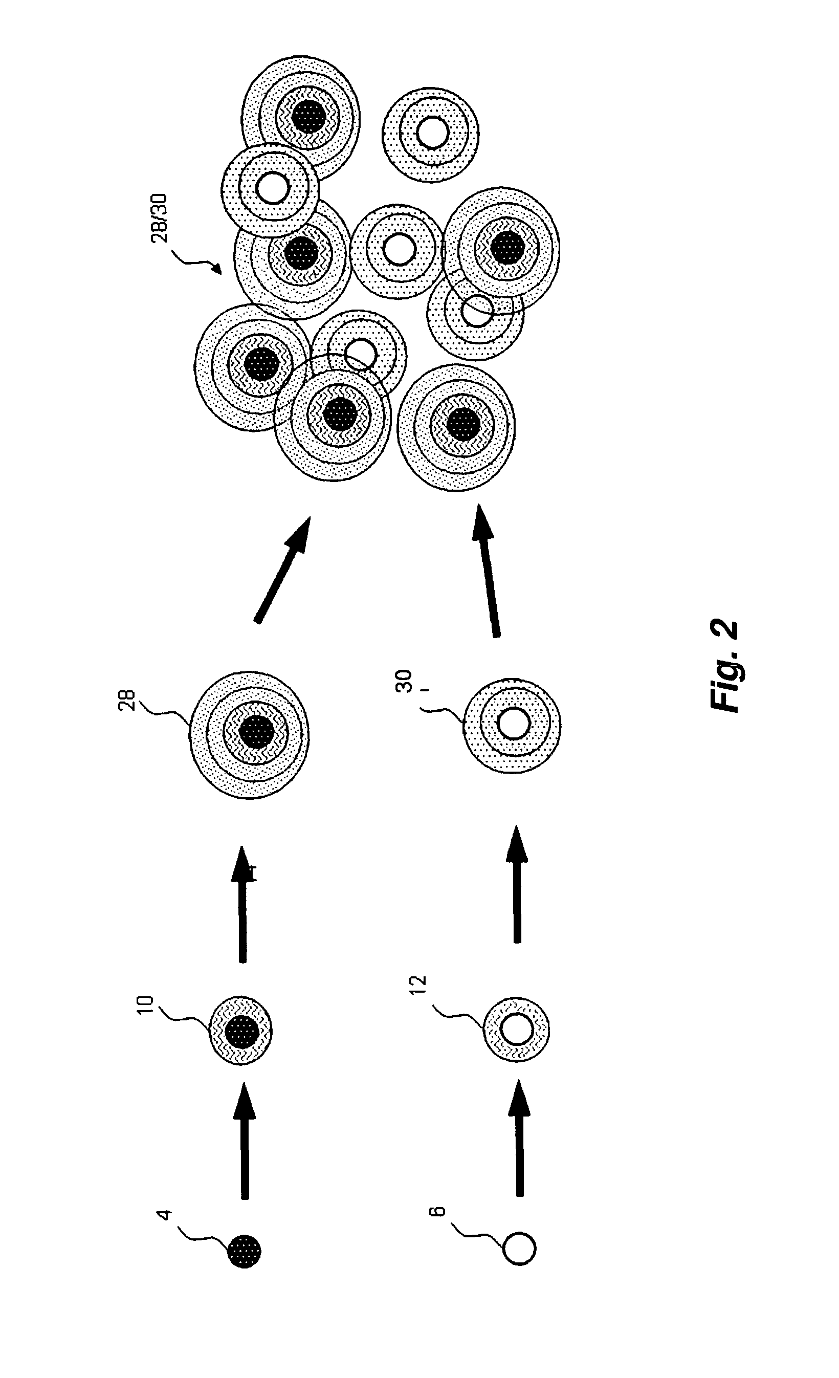
A method of producing composites of micro-engineered, coated particulates embedded in a matrix of metal, ceramic powders, or combinations thereof, capable of being tailored to exhibit application-specific desired thermal, physical and mechanical properties to form substitute materials for nickel, titanium, rhenium, magnesium, aluminum, graphite epoxy, and beryllium. The particulates are solid and / or hollow and may be coated with one or more layers of deposited materials before being combined within a substrate of powder metal, ceramic or some combination thereof which also may be coated. The combined micro-engineered nano design powder is consolidated using novel solid-state processes that prevent melting of the matrix and which involve the application of varying pressures to control the formation of the microstructure and resultant mechanical properties.

Description

CROSS REFERENCE TO RELATED APPLICATION[0001]This application claims priority under 35 USC 119(e) of Provisional Patent Application Ser. No. 61 / 125,243 filed Apr. 22, 2008, entitled “Multifunctional High Strength Metal Composite Materials” which is hereby incorporated by reference in its entirety.GOVERNMENT RIGHTS CLAUSE[0002]The U.S. Government has a paid-up license in this invention and the right in limited circumstances to require the patent owner to license others on reasonable terms as provided for by the terms of Missile Defense Agency SBIR Contracts HQ0006-06-C-7351 and HQ0006-07-C7601.FIELD OF THE INVENTION[0003]The invention relates to the composition and manufacture of metals, alloys, metal matrix or cermet composites and composite materials.BACKGROUND OF THE INVENTION[0004]Prior art in the field of metal matrix composites is primarily focused on providing a material for use as a metal substitute to provide a single desired property—light weight. These composites are typica...

Claims


Application Information

Patent Timeline
IPC IPC(8): B22F1/02B22F1/16B22F1/17B22F1/18
CPCB22F3/17B22F1/0003B22F1/025B22F1/02B22F2998/10B22F2003/247B22F2003/248B22F2999/00B22F2003/242Y10T428/12014B22F1/0051B22F3/04B22F3/24B22F3/02B22F3/225B22F3/15B22F3/105B22F3/1035B22F1/16B22F1/17B22F1/18B22F1/12B22F1/09B22F1/0655B22F3/20B22F3/22B22F9/04B22F2003/1051
Inventor BAKER, DEAN M.MEEKS, HENRY S.
Owner AMARANTHINE RESOURCES LLC
Learn More