Dies for shear drawing

a shear drawing and die technology, applied in the direction of drawing dies, etc., can solve the problems of non-continuous process, limitation in the commercialization of ecae, and non-uniform distribution of cross sections of material in a length direction

Active Publication Date: 2013-08-27
POHANG IRON & STEEL CO LTD
View PDF19 Cites 2 Cited by
  • Summary
  • Abstract
  • Description
  • Claims
  • Application Information

AI Technical Summary

Benefits of technology

[0013]According to an aspect of the present invention, there is provided a die for shear drawing including: a material processing channel in which a material is sheared and drawn while passing therethrough, wherein the processing channel includes an inlet path positioned at a front end thereof, and an outlet path positioned at a rear end thereof, when viewed from a movement direction of a material, the inlet path and the outlet path are connected to intersect central axes thereof at a certain angle, and the processing channel includes a cross-section reduction segment allowing an outlet cross-sectional area of the outlet path to be smaller than an inlet cross-sectional area of the inlet path to thereby draw out a material from an exit of the outlet path with the material filled therein.
[0014]According to the present invention, continuous shear deformation is possible and a filling of a material in a die is good during shear drawing such that an almost constant value of an aspect ratio in a cross section of a material may be obtained along an entire length of the material after shear drawing. As a result, ultra-fine grain refinement may be performed and mechanical properties may be improved. With respect to carbon steels subjected to spheroidizing heat treatment, effects enabling a reduction of a heat treatment temperature and a time used therefor may be obtained.

Problems solved by technology

However, even though ECAE is a good severe plastic deformation technology, a continuous process is not possible because it is an extrusion process.
Therefore, there is a limitation in the commercialization of ECAE.
However, since a material may not uniformly fill a die channel of the processing apparatus during a drawing process, i.e., a filling of a material is insufficient, there are limitations in that a cross section of the material is non-uniformly distributed in a length direction after the processing of the material, and necking is generated during the drawing of the material (see Reference [5]).
Although various apparatuses and methods capable of applying severe plastic deformation technology as well as performing a continuous process may be introduced in addition to the foregoing technology (see Reference [6]), materials having severe plastic deformation applied thereto are mainly sheets, and the apparatuses and methods do not suggest a concrete method for a material to be passed through an equal channel angle and to guarantee surface quality and cross-sectional uniformity of the sheets after processing.

Method used


Image

  • Dies for shear drawing
  • Dies for shear drawing
  • Dies for shear drawing

Examples


example 1

[0060]A shape of a die for shear drawing according to the present invention and a shape of an ECAD die having the same channel diameter as the die for shear drawing were prepared. In order to compare degrees of filling of a material between two dies, experiments were carried out by using a finite element analysis program and fabricating the dies.

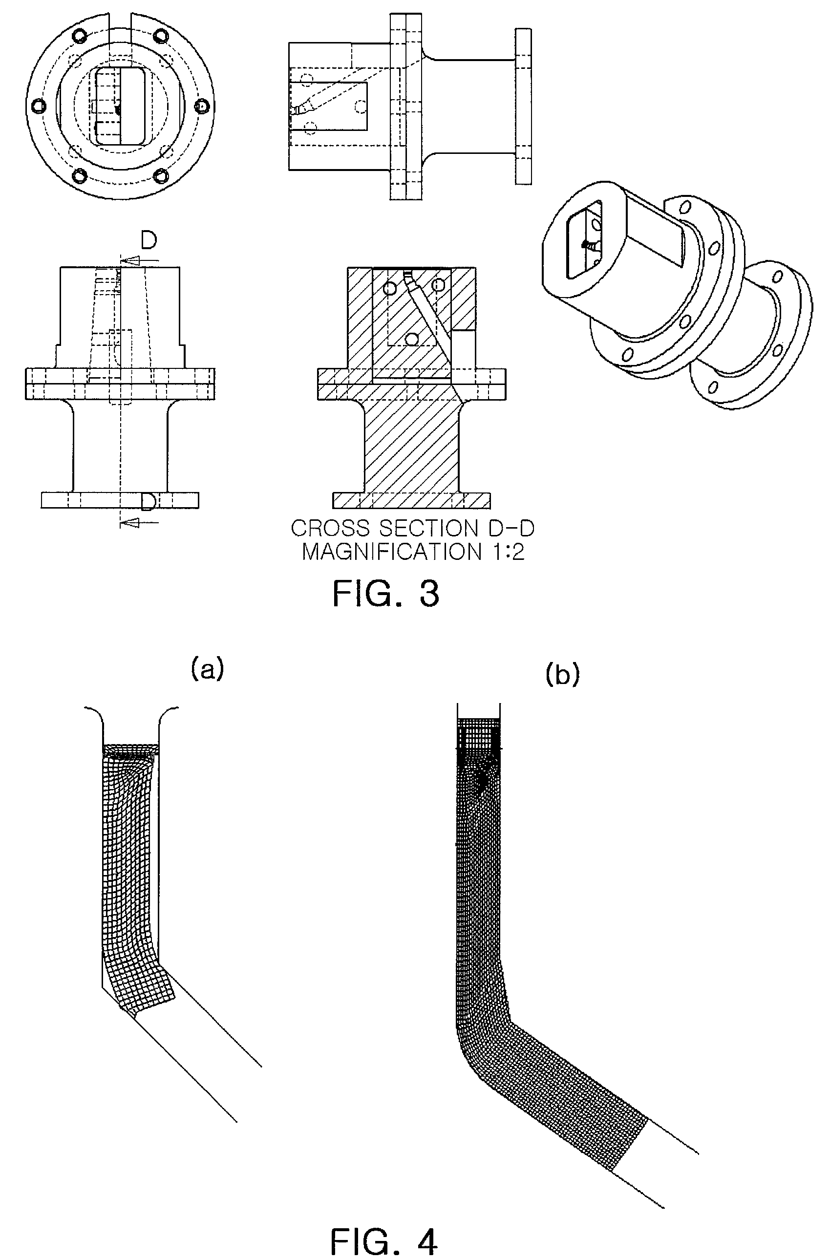
[0061]FIG. 3 illustrates a die mold and a fastening device for fabricating the die for shear drawing according to the present invention. A material used for a finite element analysis simulation and experiments of fabricating a real device was plain low carbon steel (0.1 wt % of C), and has an initial diameter of about 10 mm and a length of about 500 mm.

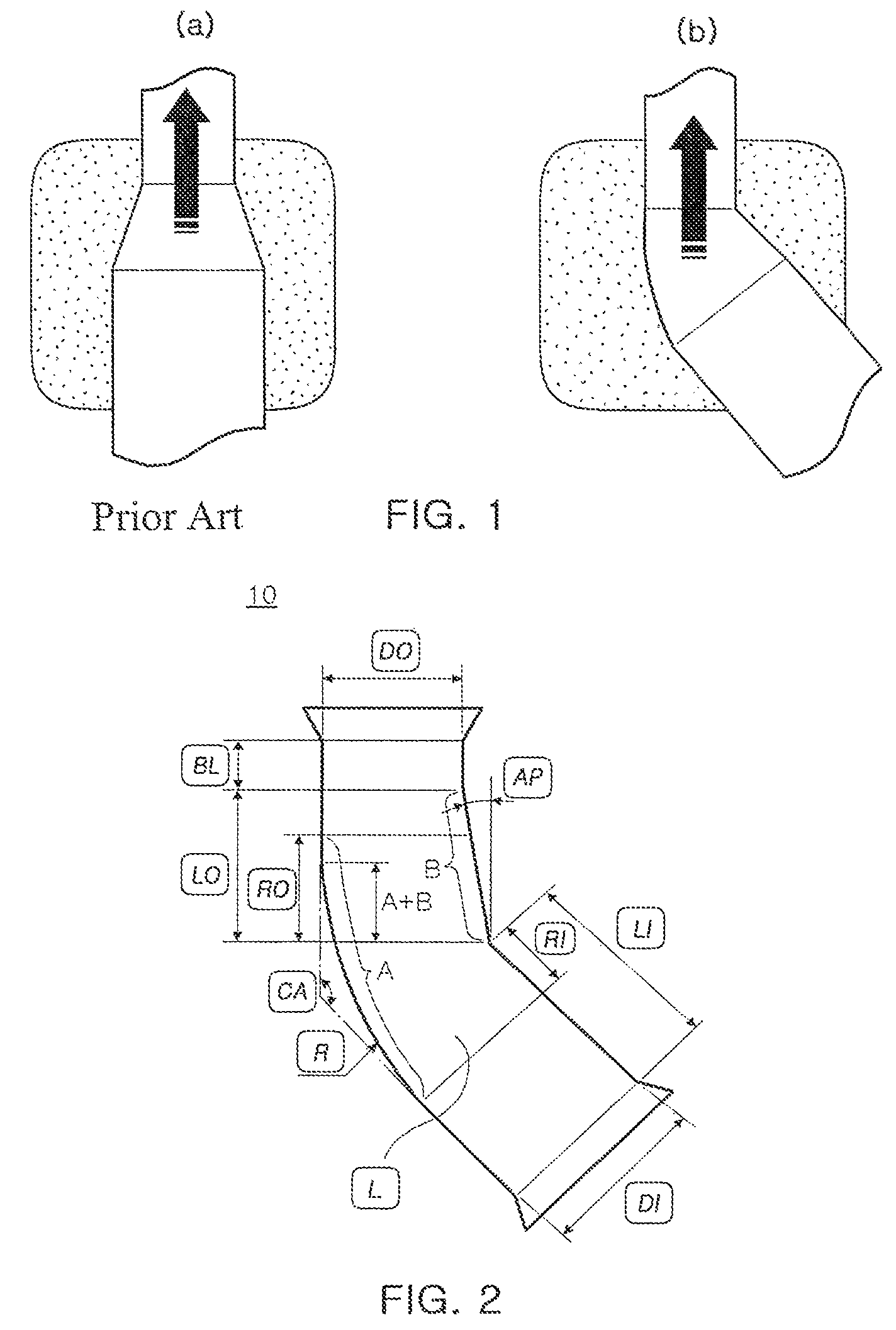
[0062]Finite element analyses were performed on the typical ECAD die having the same channel diameter and the die for shear drawing of the present invention in FIG. 3. Results of comparing the fillings of a material were presented in FIG. 4.

[0063]In FIG. 4, (a) represents a finite element anal...

example 2

[0069]Experiments for the optimization of design factor values were performed in order to design a die having the best filling of a material as in the foregoing Example 1.

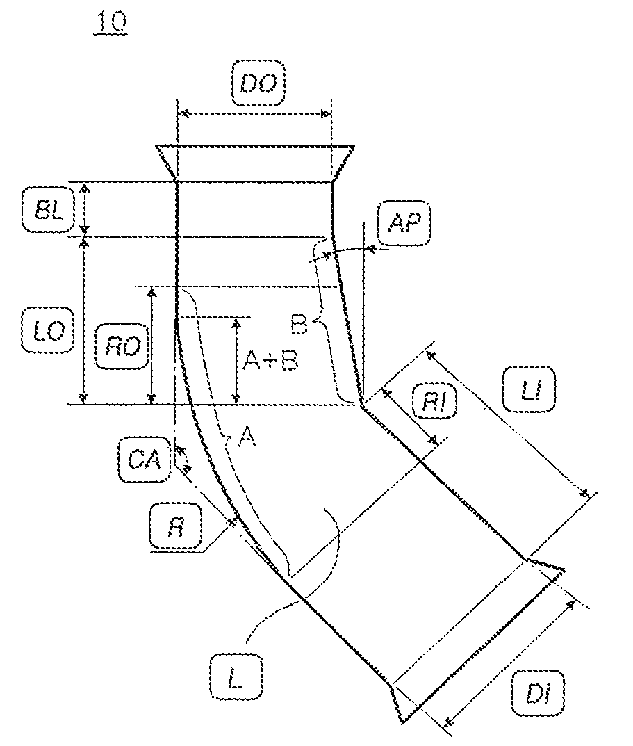
[0070]Design factors in the present Example are defined based on the drawing shown in FIG. 2, and presented below—LI: inlet path length, LO: outlet path length, R: radius of curvature at a curved portion, RI: inlet path length where R is introduced, RO: outlet path length where R ends, AP: entrance angle, BL: bearing length, CA: intersecting angle, DI: inlet diameter, DO: outlet diameter.

[0071]A finite element analysis program was used as in Example 1 to obtain conditions for the design factors having the maximum effective strain, and simulation conditions are as follows. A material diameter at an inlet of 10.0 mm, a material diameter at an outlet of 8.5 mm (a reduction ratio of 28%), an intersecting angle of 135°, a drawing speed of 100 mm / min, and a friction coefficient of 0.13 were used, and a test material used...

example 3

[0081]An optimized die was fabricated in Example 2, and various materials were deformed by shear drawing. Drawing conditions were the same as those of Example 2, and medium carbon steel (0.45 wt % of C), subjected to a spheroidizing heat treatment, was used as a workpiece.

[0082]The spheroidizing heat treatment is a process applied to a material mainly subjected to a cold forging process, and is a heat treatment process facilitating cold forging by a softening of a material. That is, the spheroidizing heat treatment is a process of transforming lamellar cementites having a hard microstructure into spherical shapes.

[0083]Although heat treatment conditions differ according to steel types or heat treatment facilities, a material during typical spheroidizing heat treatment is heated above an A1 temperature point and maintained just below the A1 temperature point for a certain period of time, and then, is stepwise cooled in a furnace. A total process may require a lengthy period of time, ...


PUM

PropertyMeasurementUnit
intersecting angleaaaaaaaaaa
slope angleaaaaaaaaaa
intersecting angleaaaaaaaaaa

Abstract

Provided is a die for shear drawing capable of performing continuous drawing and shear deformation at the same time. The die for shear drawing includes a material processing channel in which a material is sheared and drawn while passing therethrough, wherein the processing channel includes an inlet path positioned at a front end thereof, and an outlet path positioned at a rear end thereof, when viewed from a movement direction of a material. The inlet path and the outlet path are connected to intersect a central axes thereof at a certain angle, and the processing channel includes a cross-section reduction segment allowing an outlet cross-sectional area of the outlet path to be smaller than an inlet cross-sectional area of the inlet path to thereby draw out a material from an exit of the outlet path with the material filled therein.

Description

TECHNICAL FIELD[0001]The present invention relates to a die for shear drawing used for drawing a material such as a wire rod, a profile, or a rectangular bar, and more particularly, to a new die for shear drawing capable of performing ultra-fine grain refinement in a metal structure and improving mechanical properties by continuous drawing, and capable of performing continuous drawing and shear deformation simultaneously, which enables a decrease in a heat treatment temperature and a reduction of heat treatment time in carbon steels subjected to a spheroidizing heat treatment.BACKGROUND ART[0002]The present invention relates to the technical field pertaining to equal channel angular extrusion (ECAE, see References [1] and [2]), one of a range of severe plastic deformation technologies, and more specifically, to equal channel angular drawing (ECAD, see Reference [3]).[0003]ECAE is a process imparting severe plasticity, due to shear deformation, to a metallic material by extruding the...

Claims


Application Information

Patent Timeline
Patent Type & Authority Patents(United States)
IPC IPC(8): B21C23/00
CPCB21C23/001B21C3/04B21C1/003B21C3/02
Inventor RHEE, KI-HOSON, IL-HEONHWANG, JOONG-KILEE, DUK-LAK
Owner POHANG IRON & STEEL CO LTD
Why Eureka
Try Eureka