
Multi-phase selective mass transfer through a membrane

a selective mass and membrane technology, applied in the direction of membranes, vacuum distillation separation, separation processes, etc., can solve the problems of multiple failure mechanisms of membranes during use, common problems of moment materials, and low surface energy

Active Publication Date: 2013-08-06
TANGREDI PATRICIA
View PDF56 Cites 42 Cited by
  • Summary
  • Abstract
  • Description
  • Claims
  • Application Information

AI Technical Summary

Benefits of technology

The patent text describes a system that includes a membrane made of a special polymer. This membrane allows high-dipole liquids or gases to flow through it from one side to the other, like a porous pipe. The technical effect of this membrane is that it allows for selective transfer of certain substances, which can improve the efficiency and accuracy of the system.

Problems solved by technology

The acquisition of a desired concentration of a particular dipole (e.g., high-dipole) moment material from a material containing the dipole moment material is a common problem faced in many applications.
Membrane material surrounding the pores at the liquid interface on the first side of the membrane has a low surface energy and will not allow liquid to enter.
These membranes experience several failure mechanisms during use.
It is extremely difficult to re-dissolve these precipitated ions once they form the barricade.
The second failure mechanism occurs when water vapor condenses within the pores of the membrane.
These dissolved ions foul the membrane internally and are difficult, if not impossible to remove.
Unfortunately, the pressure also forces contaminants that would otherwise be too large to pass through the membrane into the pore structure reducing the efficacy of the membrane.
Such prior art reverse osmosis processes require a considerable amount of energy to force the water through the membrane.
Further, such plants are expensive due to the complexity of the piping necessary to support the pressurized operation with the necessary membrane cleaning.
The reverse osmosis process is also considered unstable because it is sensitive to type and amount of dissolved ions, organic proteins, and biota in the salt water.

Method used


Image

  • Multi-phase selective mass transfer through a membrane
  • Multi-phase selective mass transfer through a membrane
  • Multi-phase selective mass transfer through a membrane

Examples


third embodiment

[0210]Referring to FIG. 17, a vacuum assist system 500 will now be described. Like system 400, the first material enters and exits the mass exchanger 100 of the system 500 at substantially the same temperature. However, the mass exchanger 100 of the system 400 includes two evaporators 410 and 420 in a serial arrangement and the mass exchanger 100 of the system 500 includes two evaporators 510 and 560 in a parallel arrangement.

[0211]A conduit 502 transports the higher temperature first material to the mass exchanger 100. By way of a non-limiting example, the temperature of the first material in the conduit 502 may be about 45° C. By way of a further non-limiting example, the flow rate of the first material in the conduit 502 may be about 5.65 m3 / hr.

[0212]The evaporator 510 may be constructed using any suitable evaporator disclosed herein including without limitation the evaporator 280, the evaporator 310, the evaporator 410, and the evaporator 420. The evaporator 510 depicted is subs...

fourth embodiment

[0222]Referring to FIG. 18, a vacuum assist system 600 and related process will now be described. Like system 400, the first material enters and exits the mass exchanger 100 of the system 600 at substantially the same temperature. A conduit 602 transports the higher temperature first material to the mass exchanger 100. By way of a non-limiting example, the temperature of the first material in the conduit 602 may be about 45° C. By way of a further non-limiting example, the flow rate of the first material in the conduit 602 may be about 5 m3 / hr.

[0223]The mass exchanger 100 of the system 600 includes a housing 612 housing both a segregated evaporator 610 and segregated condenser 620. The segregated evaporator 610 is separated from the segregated condenser 620 by a compressor region 640 flanked on one side by a vacuum plenum 642 and on the other side by a vacuum plenum 644. The term “segregated” means that the evaporator 610 and the condenser 620 each have a different operating tempera...

fifth embodiment

[0231]A vacuum assist desalination system 700 and related process will now be described with respect to FIG. 19. The system 700 includes a mass exchanger 100 that includes an evaporator 710. A conduit 702 transports the higher temperature first material to the evaporator 710 of the mass exchanger 100. By way of a non-limiting example, the temperature of the first material in the conduit 702 may be about 45° C. By way of a further non-limiting example, the flow rate of the first material in the conduit 702 may be about 5 m3 / hr. The higher temperature first material exits the evaporator 710 through a conduit 708 that conducts the first material outside the mass exchanger 100. By way of a non-limiting example, the temperature of the first material in the conduit 708 may be about 20° C. As is apparent to those of ordinary skill, the temperature of the higher temperature first material passing through the evaporator 710 is reduced by the evaporation process occurring inside the evaporato...


PUM

PropertyMeasurementUnit
weightaaaaaaaaaa
weightaaaaaaaaaa
weightaaaaaaaaaa

Abstract

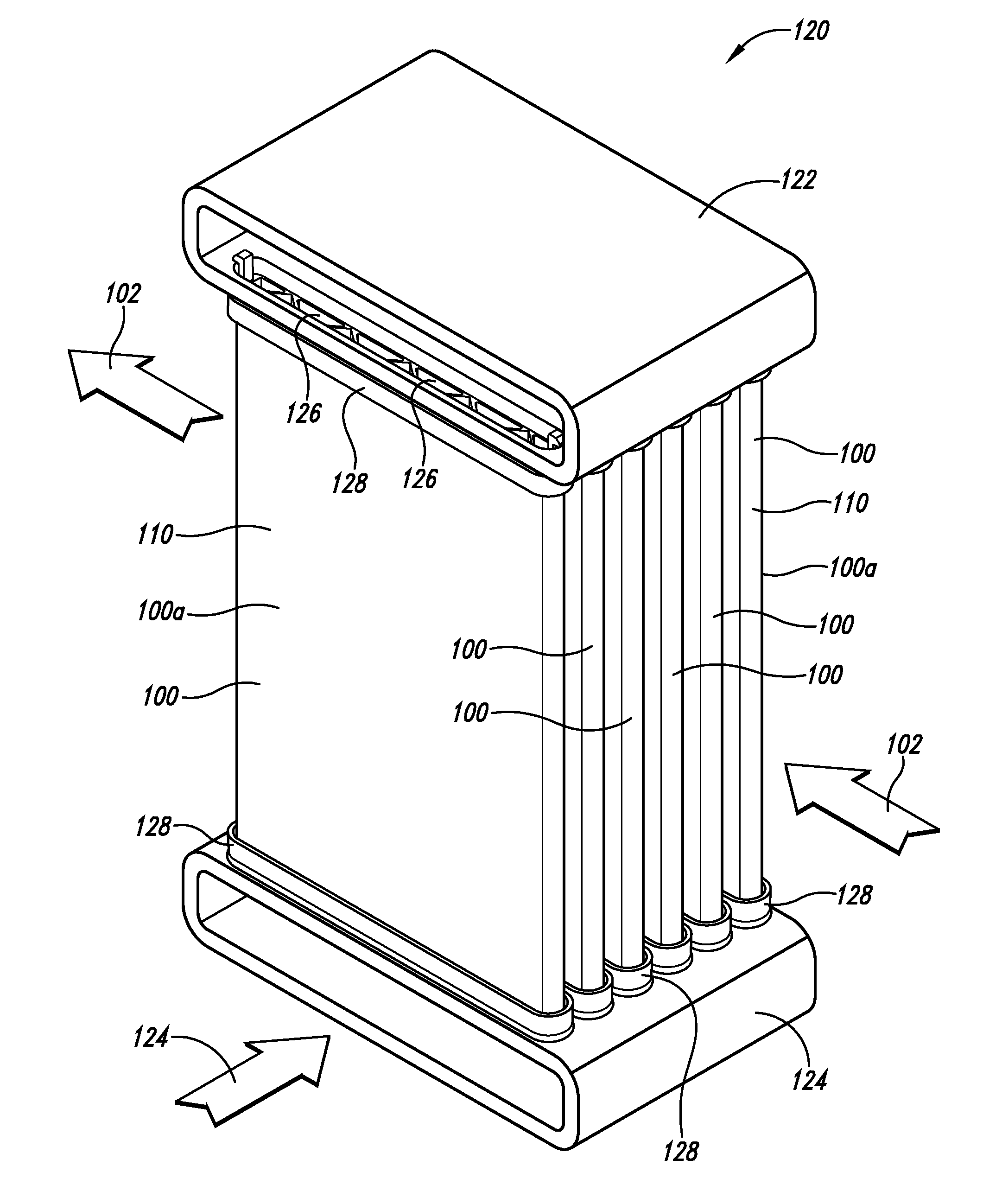
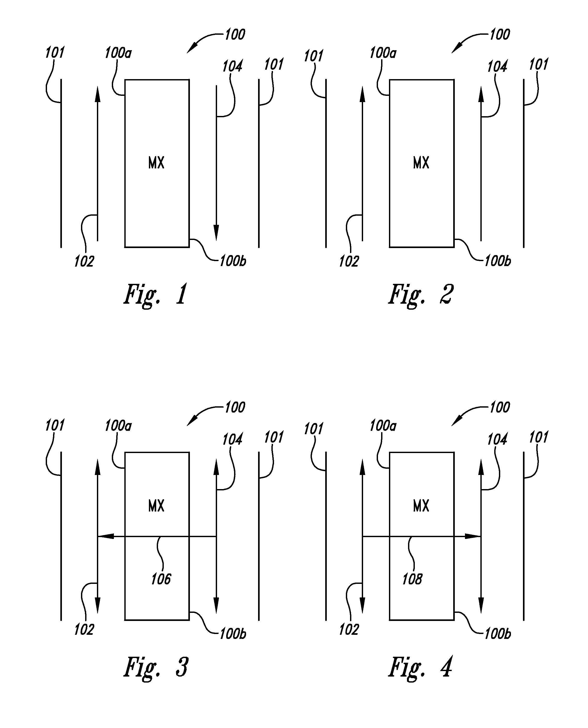
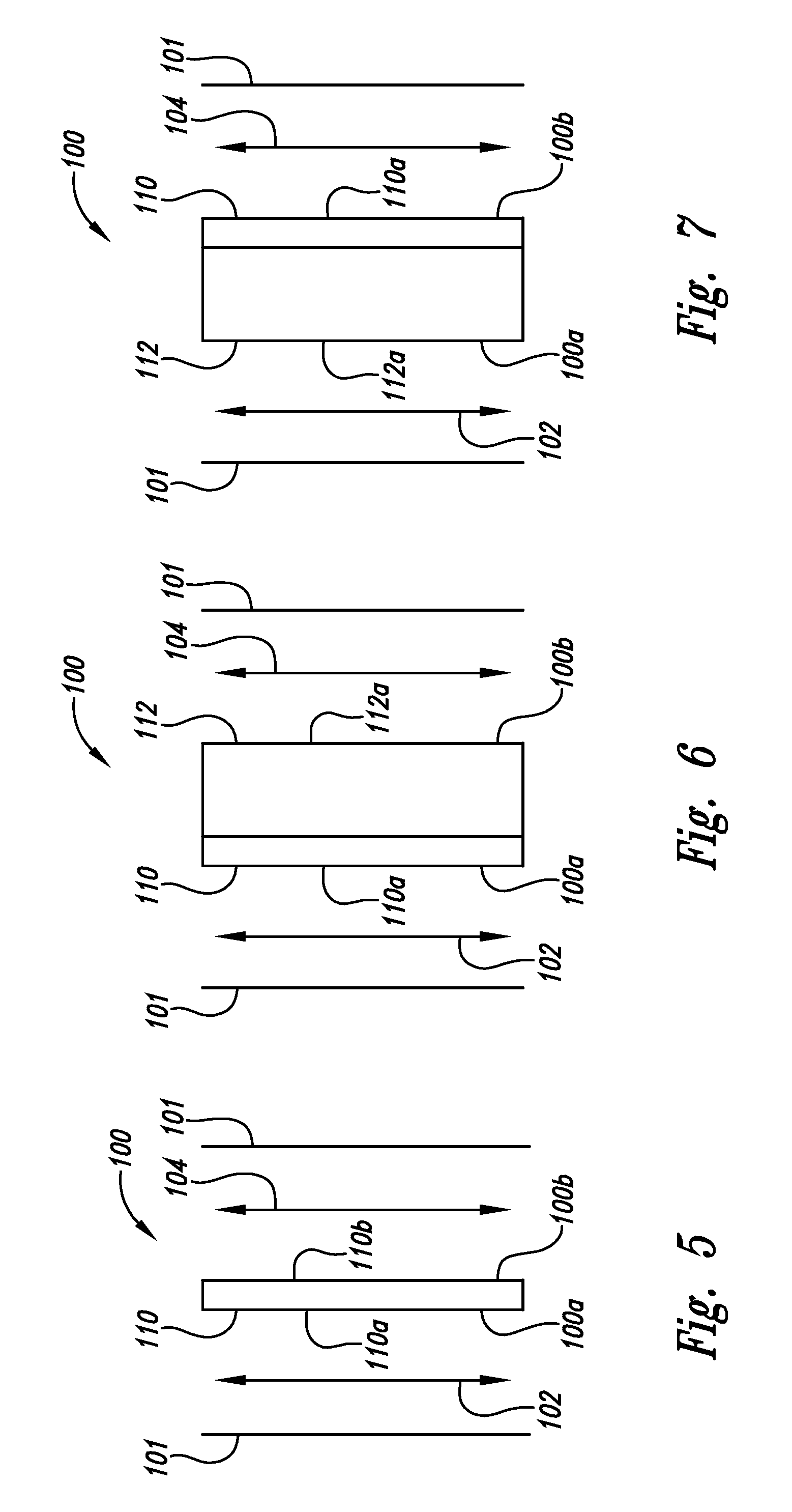
Disclosed herein are embodiments relating to particular systems comprising a selective transfer membrane that can be utilized in material separation. In certain embodiments, the membrane assembly comprises part of a desalination, distillation, liquid purification, and / or heating and cooling system. Other particular embodiments allow for a high rate of thermal capture by way of the system utilizing a selective transfer membrane. Certain preferred embodiments include a selective transfer membrane comprising an ionomeric polymer that is permeable to high dipole materials.

Description

CROSS REFERENCE TO RELATED APPLICATIONS[0001]This application is the §371 U.S. National Stage of International Application No. PCT / US2008 / 051684, filed 22 Jan. 2008, which claims the benefit of U.S. Provisional Application Ser. No. 60 / 881,690, filed Jan. 20, 2007, and U.S. Provisional Application Ser. No. 60 / 917,037, filed May 9, 2007, each of which are incorporated by reference herein in their entireties.BACKGROUND OF THE INVENTION[0002]1. Field of the Invention[0003]The present invention relates generally to the field of selective mass transfer through a membrane and is useful, inter alia, for heating, ventilation, and air conditioning (HVAC), gas conditioning, desiccation, distillation, desalination, fluid separation, and purification.[0004]2. Description of the Related Art[0005]The acquisition of a desired concentration of a particular dipole (e.g., high-dipole) moment material from a material containing the dipole moment material is a common problem faced in many applications. ...

Claims


Application Information

Patent Timeline
Patent Type & Authority Patents(United States)
IPC IPC(8): B01D1/28B01D3/40B01D17/09
CPCB01D61/364B01D63/06B01D63/085B01D71/82B01D2311/14C02F2103/08Y02A20/131Y02A20/124
Inventor EHRENBERG, SCOTT G.JOHNSON, BRIANCAO, LIWEIHUYNH, HUNGTANGREDI, TIMOTHY
Owner TANGREDI PATRICIA
Learn More