
Shock absorbing dental appliance

a dental appliance and shock absorption technology, applied in the field of dental appliances, can solve the problems of more discomfort experienced by users upon impact, failure to provide optimum comfort when a wearer experiences an impact to the jaw, and discomfort to the wearer of the devi

Inactive Publication Date: 2013-07-30
MANZO JOSEPH S
View PDF25 Cites 18 Cited by
  • Summary
  • Abstract
  • Description
  • Claims
  • Application Information

AI Technical Summary

Benefits of technology

The present invention is about a dental appliance that is designed to fit well, protect against shock, and make the wearer comfortable. The appliance has a unique structure made from a special thermoplastic material that absorbs impact well and doesn't spring back. It also has a bumper to protect the teeth, an airway opening for breathing, and a post to reinforce the airway opening and hold a tether for attaching it to a helmet. This new design makes a difference in the way the appliance fits and protects, providing better comfort for the wearer.

Problems solved by technology

That is, the shock absorbing inner plastic member exhibits greater than desired elastic rebound which, if not physically harmful, may result in discomfort to the wearer of the device upon receipt of an impact to the mandible.
Also, it is believed that the full arch core member transmits force or shock not only to the molars but also the less firmly rooted teeth which may result in more discomfort being experienced by the user upon impact.
The Shock Doctor devices, which consist of a substantially rigid dual arch inner core encased within a “boil and bite” outer layer, also fail to provide optimum comfort when a wearer experiences an impact to the jaw.
It is believed that discomfort arises from the considerable force transmission characteristic of the material selected as the inner core as well as the fact that the inner core forms the entire upper and lower tooth-receiving channels of the device.
Most notably, such devices provide no stabilization of the mandible and no frontal and lateral impact protection for the mandibular teeth.

Method used


Image

  • Shock absorbing dental appliance
  • Shock absorbing dental appliance
  • Shock absorbing dental appliance

Examples


Embodiment Construction

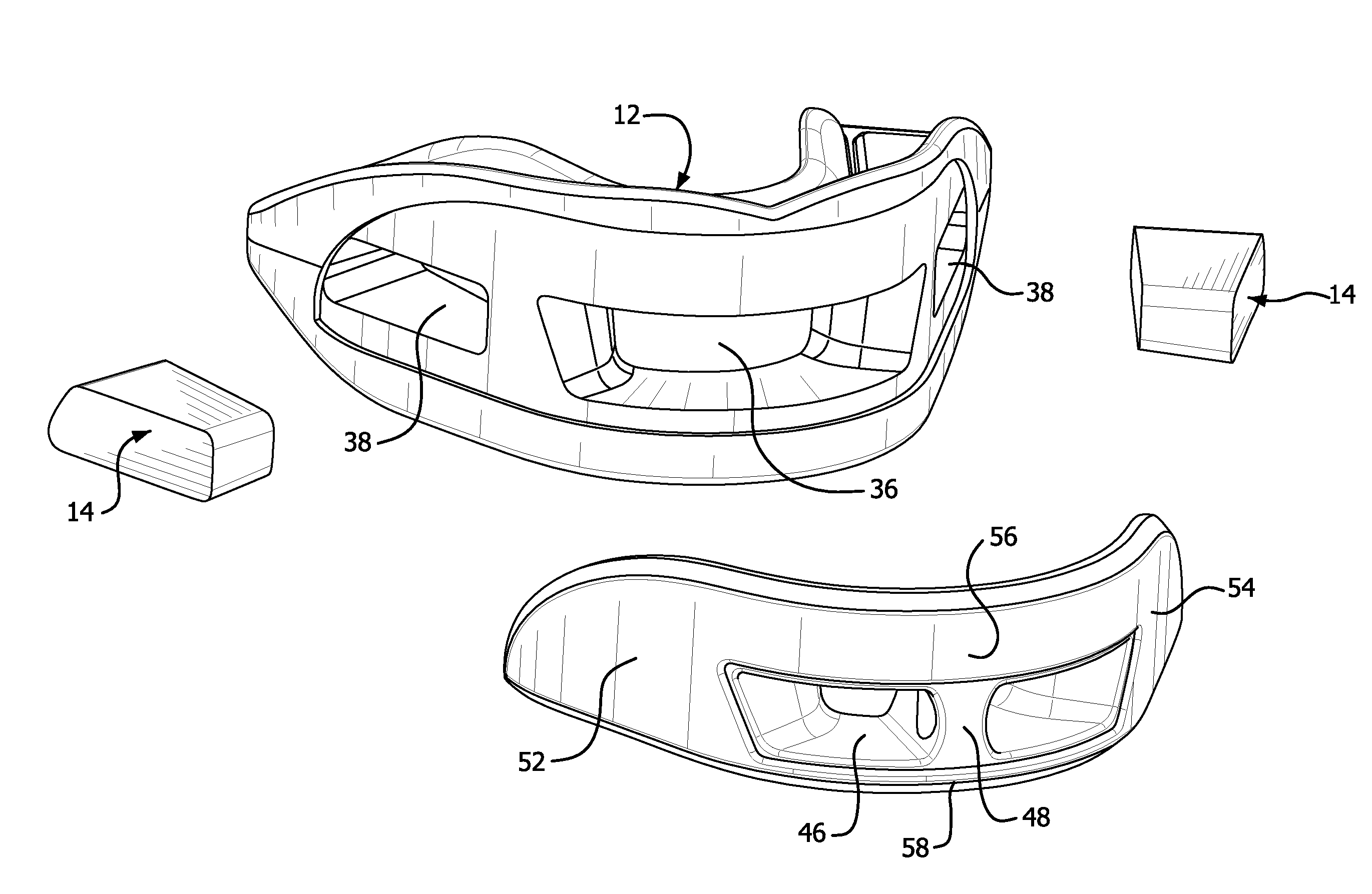
[0029]Referring to the drawings, wherein like or similar references indicate like or similar elements throughout the several views, there is shown in the figures a shock absorbing dental appliance according to the present invention, identified generally by reference numeral 10. Pursuant to a presently preferred embodiment, appliance 10 comprises a body 12 which carries a pair of impact absorbing members 14 (FIGS. 9-13) described in greater detail later herein. In addition, appliance 10 further preferably includes a bumper 16 which also is described in greater detail hereinafter.

[0030]Body 12 is preferably a unitary member including a generally horizontal arch-shaped base 18 bounded by upper and lower substantially parallel bite surfaces 20 and 22. Base 18 further includes a central anterior region 24 bounded by contiguous molar regions 26 which terminate at posterior ends 28. Lingual, labial and buccal walls project upwardly from upper bite surface 20 to form a first or upper arch-s...


PUM


Abstract

A dual arch dental appliance including a body which contains a pair of impact absorbing members located in molar regions of the arches. The impact absorbing members are selected from plastic material that exhibits high impact absorption coupled with low resilience or rebound. The result is an appliance which transfers minimal shock to the wearer. The appliance preferably further includes a bumper for providing enhanced impact protection to all of the user's upper and lower teeth. An airway opening is preferably provided to facilitate breathing when the appliance is clenched between the teeth. A post may be provided for structural reinforcement of the airway opening and, optionally, for receiving a tether for fastening the device to a helmet.

Description

CROSS REFERENCE TO RELATED APPLICATION[0001]This application claims the benefit of U.S. Provisional Application No. 61 / 223,403, filed Jul. 7, 2009.FIELD OF THE INVENTION[0002]The present invention relates in general to dental appliances and in particular to shock absorbing dental appliances.BACKGROUND OF THE INVENTION[0003]Single and dual arch mouthguards are known in the art. A single arch mouthguard receives either the upper or lower teeth of the human mouth. With varying degrees of success such devices protect the teeth from impacts. A dual arch mouthguard, in contrast, has upper and lower tooth-receiving channels which are designed to protect both the upper and lower teeth.[0004]Still other dental appliances protect not only the teeth but also the temporomandibular joint (TMJ) and surrounding tissues from injury due to impact of the lower jaw. An example of such a device is described in U.S. Pat. No. 5,636,379. As described therein, the device is similar to a dual arch mouthguar...

Claims


Application Information

Patent Timeline
Patent Type & Authority Patents(United States)
IPC IPC(8): A61C5/14
CPCA63B71/085A63B2071/086
Inventor MANZO, JOSEPH S.
Owner MANZO JOSEPH S
Learn More