
Functionally graded biocompatible coating and coated implant

a biocompatible coating and implant technology, applied in the field of biocompatible coatings, can solve the problems of loosened implant, loss of implanted teeth, and infection around the implanted tooth, and achieve the effect of reducing the usefulness of the implan

Active Publication Date: 2013-07-23
NORTH CAROLINA STATE UNIV
View PDF2 Cites 7 Cited by
  • Summary
  • Abstract
  • Description
  • Claims
  • Application Information

AI Technical Summary

Problems solved by technology

This is detrimental to the usefulness of the implant.
For example, in the case of dental implants, loosening of the implant can result in loss of the implanted tooth and can also lead to infections around the loosened implant.
Numerous problems with the HA coatings, however, have also been cited, including variation in bond strength at the coating-metal interface, variation in structural and chemical properties, and non-uniformity in coating density.
Although plasma spraying is fast and cost effective, the coatings have several flaws that could lead to implant failures.
This leads to inconsistent bonding strengths.
Further, regardless of the coating methodology, amorphous layers are generally formed on metal substrates, which have a high dissolution rate in aqueous solutions.
This heat treatment, however, causes cracks in the layer due to the thermal expansion mismatch between the coated layer and the metal substrate.
This leads to a severe reduction in bond strength.
Such thick coatings can lead to low fracture resistance.
This, along with reduced bond strength, can lead to delamination, and detached fragments have very adverse effects on the implant, as well as the tissue surrounding it.
For example, particulate debris at the bone prostheses interface with HA coated implants has been found to cause a foreign body response that is destructive to the surrounding tissues.

Method used


Image

  • Functionally graded biocompatible coating and coated implant
  • Functionally graded biocompatible coating and coated implant
  • Functionally graded biocompatible coating and coated implant

Examples


example 1

Preparation of Coated Substrate

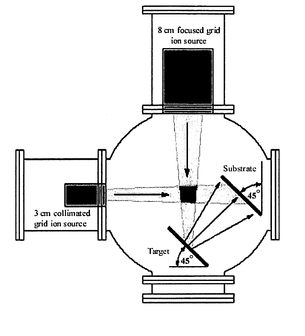
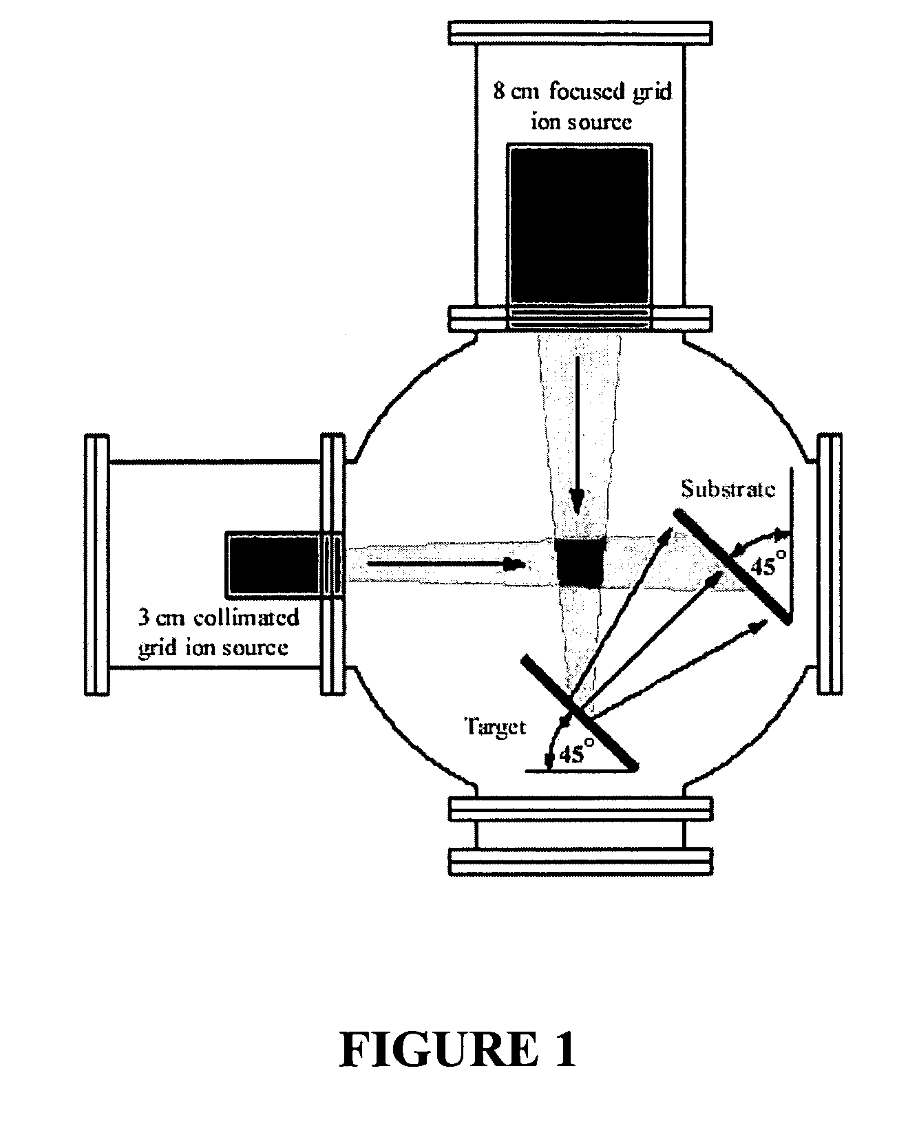
[0076]A coated substrate was prepared by depositing a hydroxyapatite film on a silicon substrate in a dual ion beam sputtering system as shown in FIG. 1. The base pressure of the dual ion beam sputtering system was set at 9×10⁻⁷ Torr. A 15.24 cm diameter hydroxyapatite target recessed into a stainless steel holder was used as the hydroxyapatite source.

[0077]For the duration of the deposition process, the primary ion source was set at 1000V, and a gas flow of 3 sccm was provided to each ion source bringing the background pressure of the system to approximately 4×10⁴ Torr. The assist beam was initially set to 1000V. After 10 minutes of deposition, the assist beam was set to 400V, and it remained at that setting for the remainder of the deposition.

[0078]For the first 2 hours of deposition, the substrate heater was set at 700° C. After two hours of deposition, the substrate heater was reduced to 500° C. After an additional 2 hours, the heater was completel...

example 2

Structural Analysis of Hydroxyapatite Film on Coated Substrate

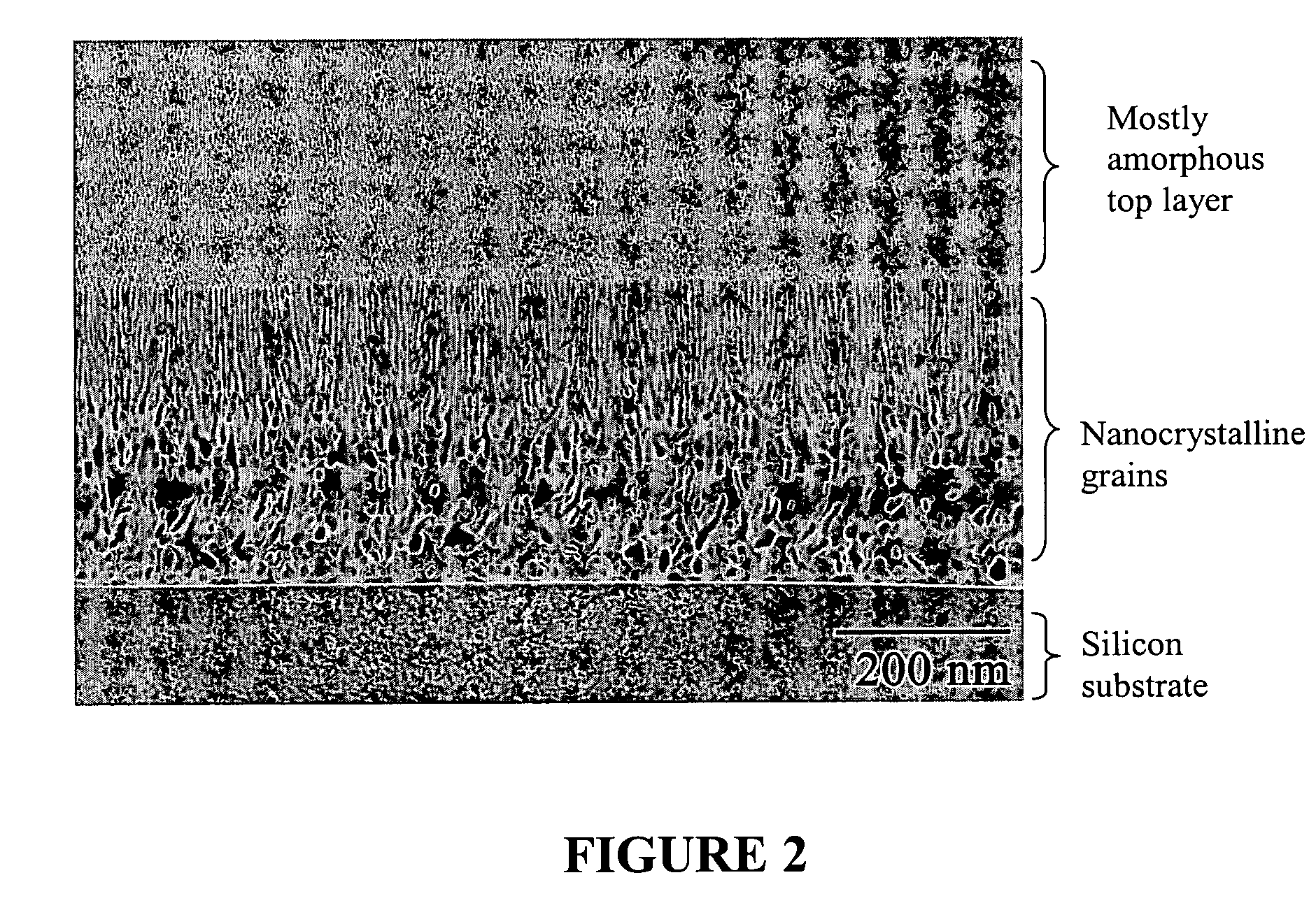
[0080]The cross-sectional structure of the HA film prepared in Example 1 is shown in FIG. 2. The figure provides a TEM cross-sectional image of the functionally graded HA film. The film has an overall thickness of 875 nm, and on visual inspection, the film can be seen to include a number of distinct layers. The silicon substrate is covered by a thin amorphous layer of silicon dioxide (about 12 nm thick), followed by a coarse crystalline HA layer (210 nm thick). On top of that is a fine crystalline HA layer (140 nm thick), followed by a layer of amorphous HA mixed with very fine nano-structure HA grains (513 nm thick).

[0081]As can be seen in FIG. 2, the degree of crystallinity decreases from the bottom layer (in contact with the substrate) to the top layer. The bottom layer comprises predominately crystalline HA, while the top layer comprises predominately amorphous HA. Further, the crystal grain size also decreases from t...

example 3

Preparation of Comparative Coated Substrate

[0084]For use as a comparative to the coating of the invention, a calcium phosphate film was sputtered on a cleaned glass surface using a CMS-18 radiofrequency magnetron sputtering system. The target used in the sputtering process was a 101.6 mm diameter sintered HA target on a copper backing. The base pressure in the sputtering chamber was about 6.5×10⁻⁶ Torr. Sputter-deposition was performed using a process pressure of about 1.0 to about 1.5 mbar and a sputtering power of 200 W for 7 hours. A coating rate of 60 nm per hour was observed. After sputtering, the coated samples were subjected to post-deposition heat treatment at 500° C. for 30 minutes using a Thermolyne 48000 furnace to prepare a crystalline phase coating. The post-deposition heat treatment resulted in a crystallinity of 62% (+ / −2%), which was confirmed by X-ray diffraction.


PUM

PropertyMeasurementUnit
crystal diameteraaaaaaaaaa
thicknessaaaaaaaaaa

Abstract

The present invention provides a biocompatible coating comprising calcium phosphate that is functionally graded across the thickness of the coating. The coating, which preferably includes hydroxyapatite, is particularly useful for coating implants, such as dental or orthopedic implants. The functionally graded coating is generally crystalline near the interface with the surface of the implant, with crystallinity and crystal diameter decreasing toward the outer layer of the coating. The invention further provides methods for preparing a coated implant comprising a functionally graded calcium phosphate coating thereon.

Description

FIELD OF THE INVENTION[0001]The present invention relates to biocompatible coatings. In particular, the invention is related to implants coated with a biocompatible calcium phosphate coating and methods of preparation of such coated implants.BACKGROUND OF THE INVENTION[0002]Various types of implants are commonly used in biomedical applications, particularly in the dental and orthopedic fields. Often, implants are associated with use in areas of hard tissue (i.e., cartilage, bone, etc.), and the implants generally comprise hard, durable materials, such as metals, particularly titanium.[0003]Uncoated titanium implants are normally covered by a bioinert surface of titanium dioxide. The presence of the bioinert surface structure prohibits biointegration of the implant by the surrounding tissue. Accordingly, the body responds to the foreign object by isolating the implant with a flexible layer of fibrous tissue that can easily cause an implant to loosen. This is detrimental to the useful...

Claims


Application Information

Patent Timeline
Patent Type & Authority Patents(United States)
IPC IPC(8): A61F2/00A61K9/16
CPCA61C8/0012A61C8/0013A61F2/30767A61L27/32A61F2/0077A61F2/3094A61F2002/30028A61F2002/30029A61F2002/30929A61F2002/3098A61F2250/0051A61F2310/00796
Inventor RABIEI, AFSANEHCUOMO, JEROME J.THOMAS, BRENT C.
Owner NORTH CAROLINA STATE UNIV
Learn More