
Resonator for a vibratory sensor of an angular parameter

a vibratory sensor and angular parameter technology, applied in the direction of generator/motor, acceleration measurement using interia forces, instruments, etc., can solve the problems of reducing the performance of the resonator, reducing the quality of the resonator, and reducing the mechanical damping and electrical damping.

Active Publication Date: 2013-07-23
SAFRAN ELECTRONICS & DEFENSE
View PDF26 Cites 8 Cited by
  • Summary
  • Abstract
  • Description
  • Claims
  • Application Information

AI Technical Summary

Benefits of technology

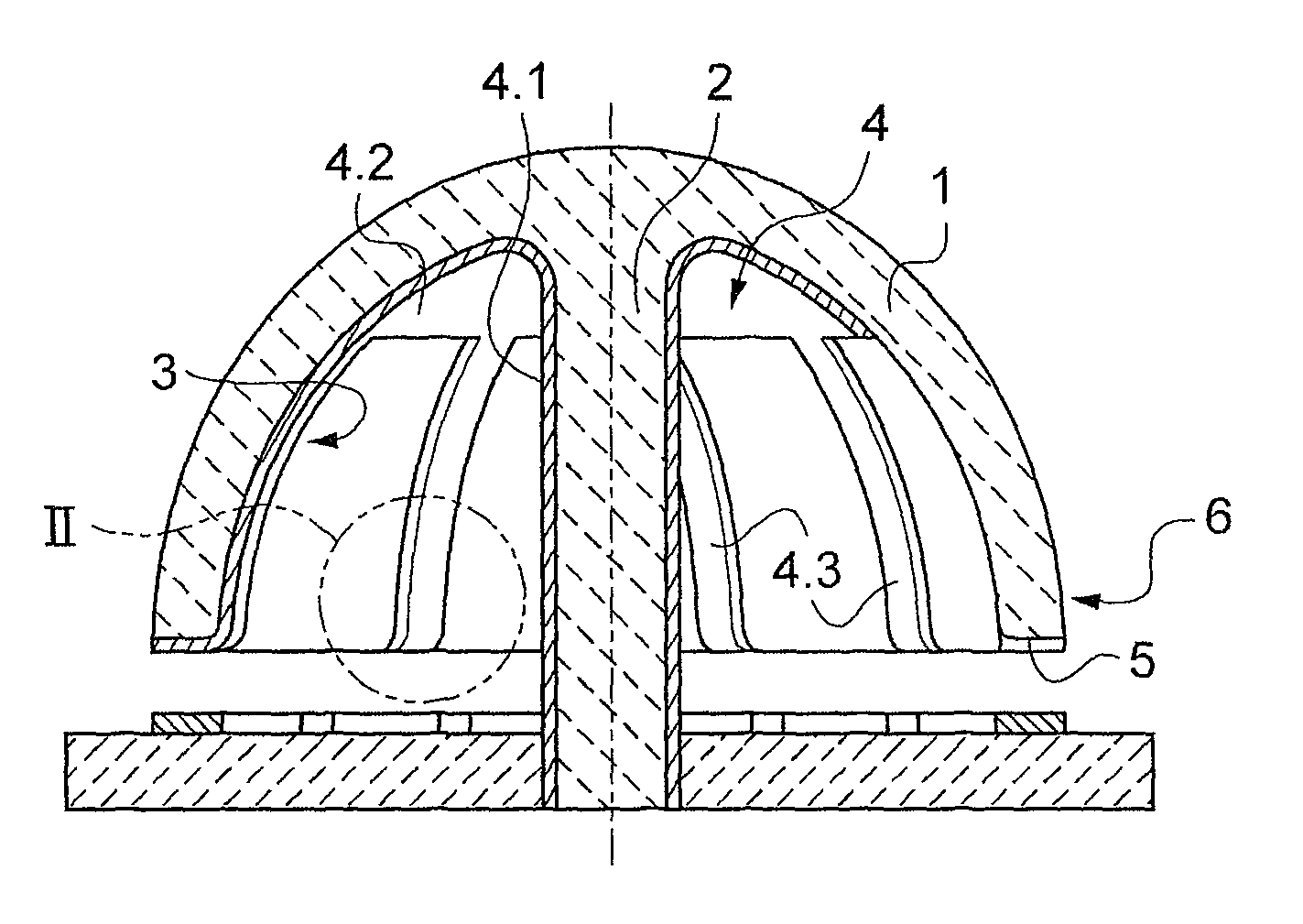
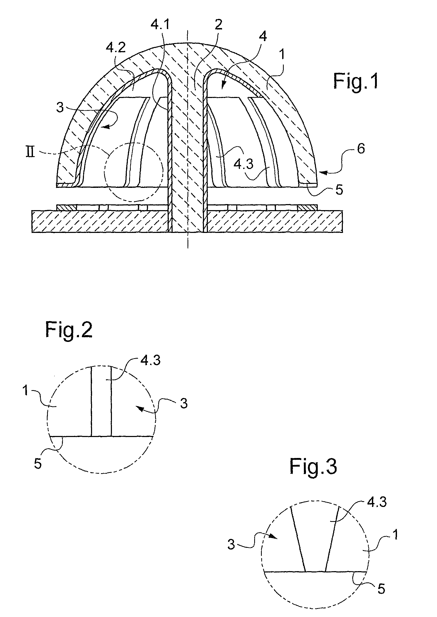
[0006]Thus, the conductive layer does not cover all of the portion of the bell in the vicinity of the peripheral edge where deformation is the greatest and where damping thereof is the most penalizing, even though all that is required in order to convey current to the electrodes formed on the peripheral edge is electrical continuity. By using a number of branches that is prime and not less than seven it is possible to ensure sufficient conduction of electricity while limiting the influence of the conductive layer on the mechanical behavior of the bell. In particular, such a number limits the risk of the conductive layer giving rise to subharmonics in the first, second, third, and fourth geometric orders. This also increases tolerance to fabrication defects, and in particular to a defect in the centering of the conductive layer relative to the bell.
[0008]The influence of the conductive layer on the mechanical behavior of the bell is minimized and fabrication of the conductive layer remains relatively easy, particularly concerning the preparation of the mask for depositing the conductive layer.
[0010]This embodiment presents a good compromise for obtaining low mechanical and electrical damping while ensuring that the resonator remains relatively easy to fabricate. In the vicinity of the pole of the bell, the conductive layer covers substantially all of the surface of the bell, but without penalizing the performance of the resonator, since damping at the pole of the bell has no effect on performance.

Problems solved by technology

The conductive layer is generally made of metal, but presents the drawback of conferring both mechanical damping and electrically damping (as a result of the resistive losses produced by detection current flowing in the conductive layer in the vicinity at the equator).
The damping of the vibrations also makes it necessary to increase the energy for sustaining vibration, and above all it degrades the performance of the resonator by increasing drift if the resonator presents a geometrical harmonic defect of order four.

Method used


Image

  • Resonator for a vibratory sensor of an angular parameter
  • Resonator for a vibratory sensor of an angular parameter

Examples


Embodiment Construction

[0022]With reference to FIGS. 1 and 2, the resonator of the invention is intended for use in known manner in an angular parameter sensor such as a free gyro or a rate gyro, both of which are devices that are known in themselves and neither the structure nor the operation thereof is described herein.

[0023]The resonator in accordance with the invention comprises a bell 1 of hemispherical shape provided at its center with a stem 2 that projects from the inside surface 3 of the bell 1. The bell 1 and the stem 2 are made by machining silica.

[0024]The resonator comprises a conductive layer given overall reference 4 and comprising a portion 4.1 covering the stem 2, an annular central portion 4.2 extending the portion 4.1 around the base of the stem 2, and seven branches 4.3 extending from the portion 4.2 to the peripheral edge 5 of the bell 1. The branches 4.3 extend substantially along meridians of the bell 1 and in this example they have parallel longitudinal edges. The width of the bran...


PUM


Abstract

A resonator for an angular parameter sensor, the resonator comprising a bell of electrically-insulating material provided with a central stem and an electrically-conductive layer, the conductive layer comprising branches extending from a central portion of the bell to a peripheral edge of the bell, the number of said branches being a prime number not less than seven.

Description

[0001]This Nonprovisional application claims priority of Provisional Application No. 61 / 172,480, filed on Apr. 24, 2009, under 35 U.S.C. 1.119(e), the entire contents of which are hereby incorporated by reference.[0002]The present invention relates to a resonator for a vibratory sensor of an angular parameter, such as a rate gyro or a free gyro.BACKGROUND OF THE INVENTION[0003]In general, a resonator for a rate gyro or a free gyro comprises a hemispherical bell provided with a central stem that is fastened to a bell support part. The bell is made of an electrically-insulating material and is uniformly coated in an electrically-conductive layer so as to define electrodes at a peripheral edge of the bell, which electrodes face electrodes on a support part. The electrodes are powered to cause the bell to be deformed into an ellipse and in order to detect the orientation of the ellipse. The material used for the bell is generally silica that guarantees accuracy for the sensor by virtue ...

Claims


Application Information

Patent Timeline
Patent Type & Authority Patents(United States)
IPC IPC(8): G01C19/00G01C19/5691
CPCG01C19/5691
Inventor VANDEBEUQUE, PAULJEANROY, ALAIN
Owner SAFRAN ELECTRONICS & DEFENSE
Learn More