
Aircraft side fairing

a technology for aircraft and side panels, applied in the field of aircraft side panels, can solve the problems of reducing the space provided in the passenger cabin, increasing the weight of the aircraft, and reducing the aircraft performance, so as to improve the insulation properties and avoid the disadvantages of conventional side panels

Active Publication Date: 2013-07-23
AIRBUS OPERATIONS GMBH
View PDF24 Cites 19 Cited by
  • Summary
  • Abstract
  • Description
  • Claims
  • Application Information

AI Technical Summary

Benefits of technology

The invention is an aircraft side fairing that avoids the insulation and weight issues of conventional fairings. The fairing has a hollow chamber that is under vacuum and is surrounded by a gastight film to maintain the vacuum. The fairing also has a high degree of reflectivity of heat radiation to further reduce heat loss. With this design, the insulating layers can be reduced, and the aircraft cabin can be installed in the aircraft fuselage to a lesser depth and a spacious aircraft cabin can be provided. The use of VIP panels as core material is advantageous as they have good acoustic damping properties and contain microporous material such as silica.

Problems solved by technology

A drawback is that, due to the arrangement of core material and air chambers between the two cover layers, a material-specific thermal conduction value is produced which has a thermal conductivity of approx.
The installation of secondary insulation between the primary insulation and the core material means that a construction space is additionally required, thus reducing the space provided in the passenger cabin and increasing the weight of the aircraft.
Additional weight at the same time means losses in the aircraft performance.
In addition, the installation of additional insulation in the form of secondary insulation disadvantageously requires a separate manufacturing step during the production of a side wall panel.

Method used


Image

  • Aircraft side fairing
  • Aircraft side fairing
  • Aircraft side fairing

Examples


Embodiment Construction

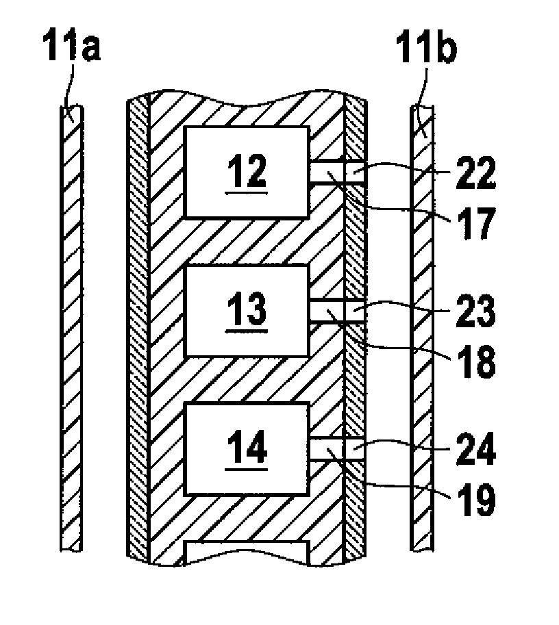
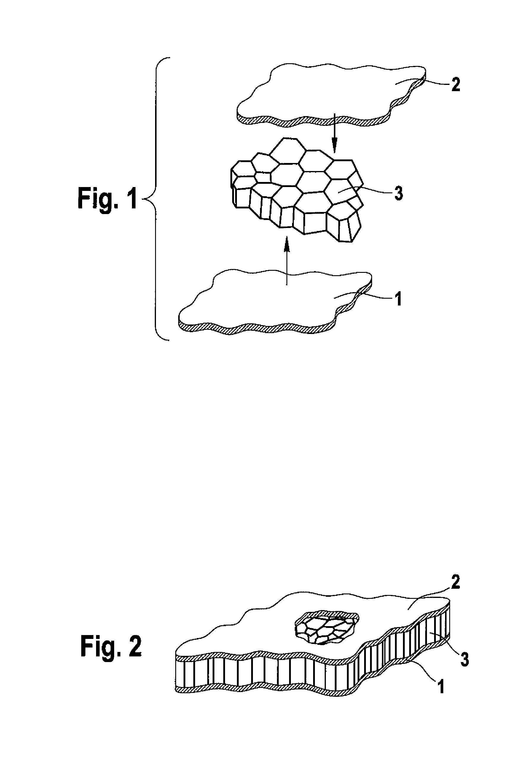
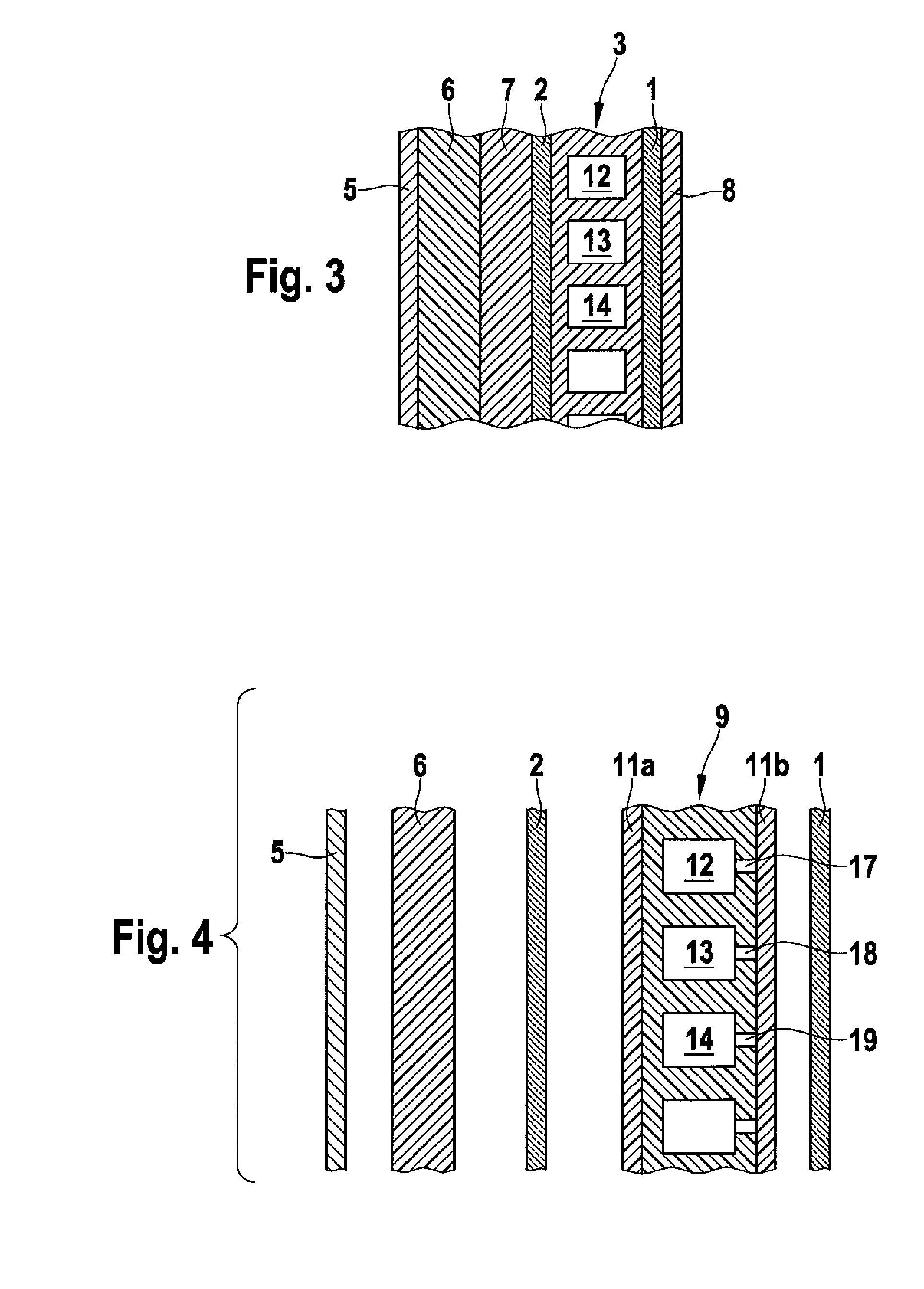
[0024]Reference is made below to FIGS. 1 to 3 which show a sectional illustration of a conventional side fairing. According to FIG. 1, the core material for an aircraft side fairing comprises a first cover layer 1 and a second cover layer 2 between which a core material 3 in the form of hollow chambers, which are located in a plane, if appropriate a curved plane, and have a honeycomb structure, is arranged. The honeycomb structure 3 and the hollow chambers formed by the latter are composed of a resin-impregnated, nonmetallic material while the cover layers 1, 2, which are adhesively bonded on to the hollow chambers 3, are produced from glass fibre fabric impregnated with synthetic resin. FIG. 2 shows the structure produced from the components 1, 2, 3 according to FIG. 1 after adhesive bonding, from which it is apparent that the cover layers 1, 2 are provided largely parallel to each other and enclose the hollow chambers 3 in the manner of a sandwich. The cover layers 1, 2 and the ho...


PUM

PropertyMeasurementUnit
Shapeaaaaaaaaaa
Vacuumaaaaaaaaaa
Optical reflectivityaaaaaaaaaa

Abstract

The invention relates to an aircraft side fairing, with a component (9) in the form of individual hollow chambers (12, 13, 14) which are arranged essentially in a preferably curved plane and are arranged between two cover layers (1, 2), wherein a gastight film which completely encases the component (9) with the hollow chambers (12, 13, 14) is provided and, after application of a vacuum to evacuate the hollow chambers (12, 13, 14), surrounds the component (9) with the hollow chambers in a gastight manner.

Description

[0001]This application claims the benefit of German Application DE 10 2006 028 956.0, filed Jun. 23, 2006, and the U.S. Provisional Application Ser. No. 60 / 815,949, filed Jun. 23, 2006.FIELD OF THE INVENTION[0002]The invention relates to an aircraft side fairing with a core material, in particular in the form of individual chambers which are arranged essentially in a plane and are enclosed between two cover layers, with an insulating layer facing the outside of the aircraft and a decorative layer facing the aircraft cabin.BACKGROUND OF THE INVENTION[0003]Known aircraft side fairings are composed of a core material, in particular in the form of individual chambers which are arranged essentially in a plane and are enclosed between two cover layers, with an insulating layer facing the outside of the aircraft and a decorative layer facing the aircraft cabin. The core material in this case is composed of chambers, in particular of honeycomb hollow chamber structures of resin-impregnated ...

Claims


Application Information

Patent Timeline
IPC IPC(8): E04C2/54
CPCB32B3/12B32B3/26B64C1/066F16L59/065B64C1/40Y10T428/231Y02T50/46Y02T50/40
Inventor MUELLER, RAINERMUEHLTHALER, GEORG
Owner AIRBUS OPERATIONS GMBH
Learn More