
Optical device and projection device

a projection device and optical technology, applied in static indicating devices, non-linear optics, instruments, etc., can solve the problem of difficult to keep each polarization element in position, and achieve the effect of improving image quality and preventing misregistration

Inactive Publication Date: 2013-07-09
SONY CORP
View PDF21 Cites 7 Cited by
  • Summary
  • Abstract
  • Description
  • Claims
  • Application Information

AI Technical Summary

Benefits of technology

[0017]The embodiments of the present invention described above include the securing member which simultaneously secures each of the polarization elements. The securing member is secured to the light synthesis device. Therefore, each of the polarization elements is simultaneously secured to the securing member which is a positional reference, thus reducing parts to be secured (parts where an adhesive is used) between each of the polarization elements and the light synthesis device.
[0018]According to the embodiments of the present invention, there are fewer parts to be secured (parts where an adhesive is used) between each of the polarization elements and the light synthesis device. Therefore, displacement at the time of assembly and displacement due to thermal expansion of an adhesive at the time of use can be reduced significantly. As a result, misregistration can be prevented to improve image quality.

Problems solved by technology

However, with a technique of Japanese Unexamined Patent Application Publication No. 2006-195267, it is difficult to keep each polarization element in position such that respective rays of reflected light are synthesized into one ray of image light.
Specifically, there is a problem in positional accuracy between the polarization element and the spacer plate and positional accuracy between the spacer plate and the cross-dichroic prism, causing displacement at the time of assembly or misregistration which prevents one ray of image light from being formed through synthesis due to thermal expansion at the time of use.

Method used


Image

  • Optical device and projection device
  • Optical device and projection device
  • Optical device and projection device

Examples


first embodiment

1. First Embodiment

Configuration Example of an Optical Device

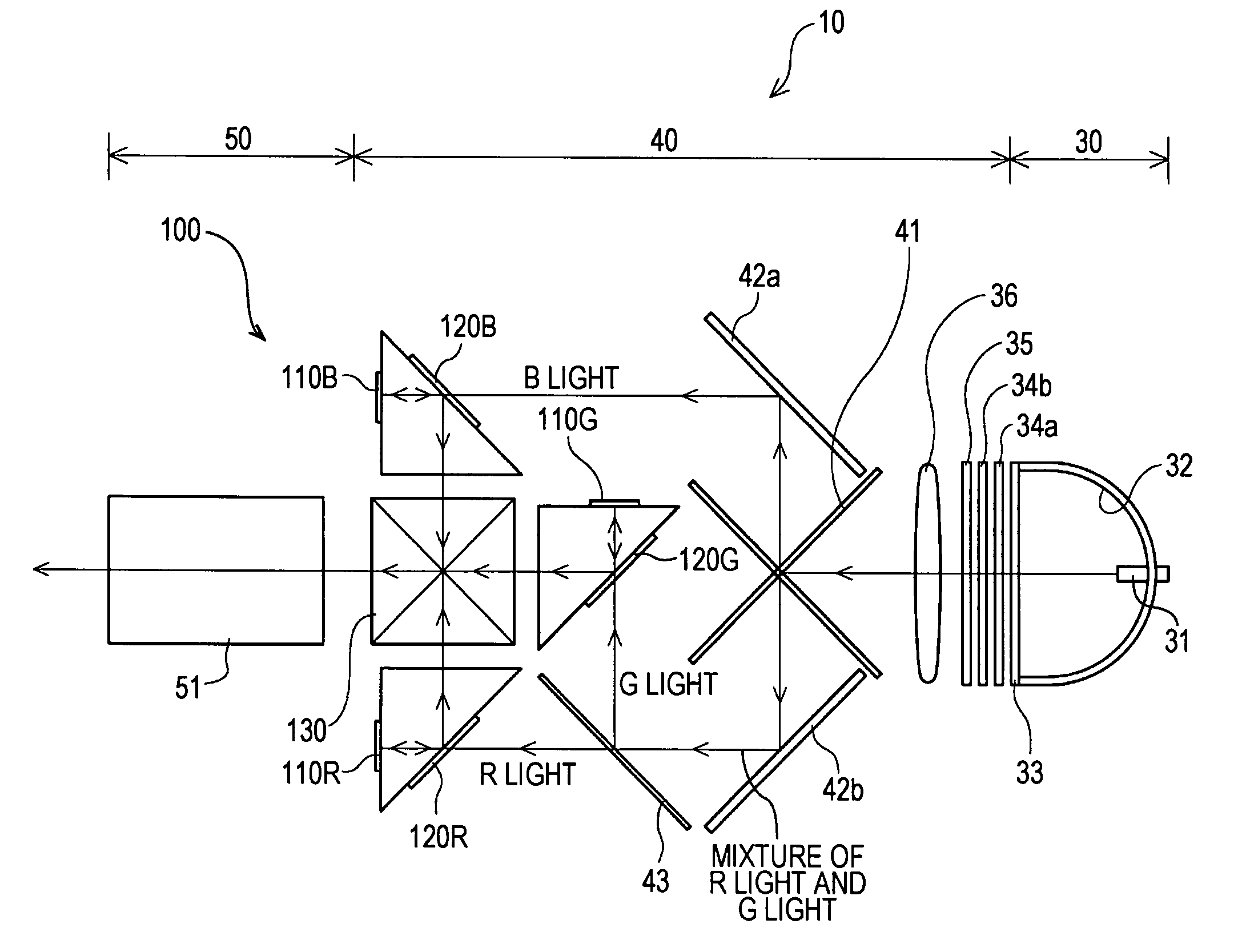
[0049]FIG. 4 is a perspective view showing the optical device 100 for the liquid crystal projector 10 (see FIG. 3) as the optical device according to one embodiment (first embodiment) of the present invention.

[0050]FIG. 5 is a plan view showing the optical device 100 for the liquid crystal projector 10 as the optical device according to the embodiment (first embodiment) of the present invention.

[0051]As shown in FIGS. 4 and 5, each of the polarization elements 120R, 120G, and 120B is directly secured with an adhesive to an end surface of a pair of upper and lower spacer plates 140 formed in a flat-plate shape.

[0052]Herein, the spacer plate 140 simultaneously secures the polarization elements 120R, 120G, and 120B in such positions that the liquid crystal panels 110R, 110G, and 110B and the polarization elements 120R, 120G, and 120B correspond with each other. The polarization elements 120R, 120G, and 120B are positional ref...

second embodiment

2. Second Embodiment

Configuration Example of an Optical Device

[0059]FIG. 6 is a perspective view showing the optical device 200 for the liquid crystal projector 10 (see FIG. 3) as the optical device according to one embodiment (second embodiment) of the present invention.

[0060]FIG. 7 is a plan view showing the optical device 200 for the liquid crystal projector 10 as the optical device according to the embodiment (second embodiment) of the present invention.

[0061]The optical device 200 in the second embodiment shown in FIGS. 6 and 7 includes liquid crystal panels 210R, 210G, and 210B and polarization elements 220R, 220G, and 220B, in a similar manner to the optical device 100 in the first embodiment shown in FIGS. 4 and 5.

[0062]The polarization elements 220R, 220G, and 220B are each secured to an end surface of a pair of upper and lower spacer plates 240 formed in a flat-plate shape. Further, the pair of upper and lower spacer plates 240 are respectively secured to two opposing surf...


PUM


Abstract

An optical device includes multiple reflective spatial light modulation devices each of which applies an image signal to each of rays of incident light and rotates a polarization direction of each of the rays of incident light for a modulated output, multiple polarization elements each of which causes each polarization component of the rays of incident light in a specific direction to be transmitted and incident upon each of the spatial light modulation devices and reflects the polarization component in a direction rotated by each of the spatial light modulation devices, a light synthesis device which synthesizes multiple rays of reflected light to be output as one ray of image light, and a securing member which simultaneously secures each of the polarization elements in a position corresponding to each of the spatial light modulation devices. The securing member is secured to the light synthesis device.

Description

CROSS-REFERENCE TO RELATED APPLICATION[0001]The present application claims priority from Japanese Patent Application No. JP 2010-099274 filed in the Japanese Patent Office on Apr. 22, 2010, the entire content of which is incorporated herein by reference.BACKGROUND OF THE INVENTION[0002]1. Field of the Invention[0003]The present invention relates to an optical device and a projection device including a light synthesis device which synthesizes multiple rays of reflected light reflected by multiple polarization elements to be output as one ray of image light.[0004]2. Description of the Related Art[0005]There has been a liquid crystal projector (projection device) including a light source unit configured of a lamp or the like supported by a reflector, an image formation unit configured to form an image, and a projection unit configured of a lens or the like which projects the image. In the image formation unit, a cross-dichroic prism (light synthesis device) which synthesizes multiple r...

Claims


Application Information

Patent Timeline
Patent Type & Authority Patents(United States)
IPC IPC(8): G03B21/28G02B7/00G02B7/18
CPCG02B27/283G03B21/14H04N9/3105H04N9/3167G03B21/2073G03B21/208G03B33/12
Inventor SATO, YUJI
Owner SONY CORP
Learn More