Fluid dispense tips
What is Al technical title?
Al technical title is built by PatSnap Al team. It summarizes the technical point description of the patent document.
a technology of dispense tips and dispense tips, which is applied in the direction of metal-working tools, coatings, metal-working apparatus, etc., can solve the problems of unnecessary dispense tips, avoid buildup of hardened materials, and prolong the useful life of dispense tips
Inactive Publication Date: 2013-07-09
DL TECH
View PDF169 Cites 11 Cited by
Summary
Abstract
Description
Claims
Application Information
AI Technical Summary
This helps you quickly interpret patents by identifying the three key elements:
Problems solved by technology
Method used
Benefits of technology
The present invention provides a method for grinding a dispense tip with a longitudinally-ground taper, which reduces surface tension and improves dispensing precision. The tip is electropolished to remove tool marks and enhance surface lubricity. The dispense tip is formed in a solid unitary piece, machined from stock, which offers increased robustness and avoids inner collapse of the neck. A cleaning tool and cleaning kit are provided for maintaining the useful lifetime of the dispense tips.
Problems solved by technology
Furthermore, alignment of the neck with the body of the tip is unnecessary and complicated assembly procedures are thereby avoided.
Method used
Image
Click on the blue label to locate the original text in one second.
Reading with bidirectional positioning of images and text.
Examples
Embodiment Construction
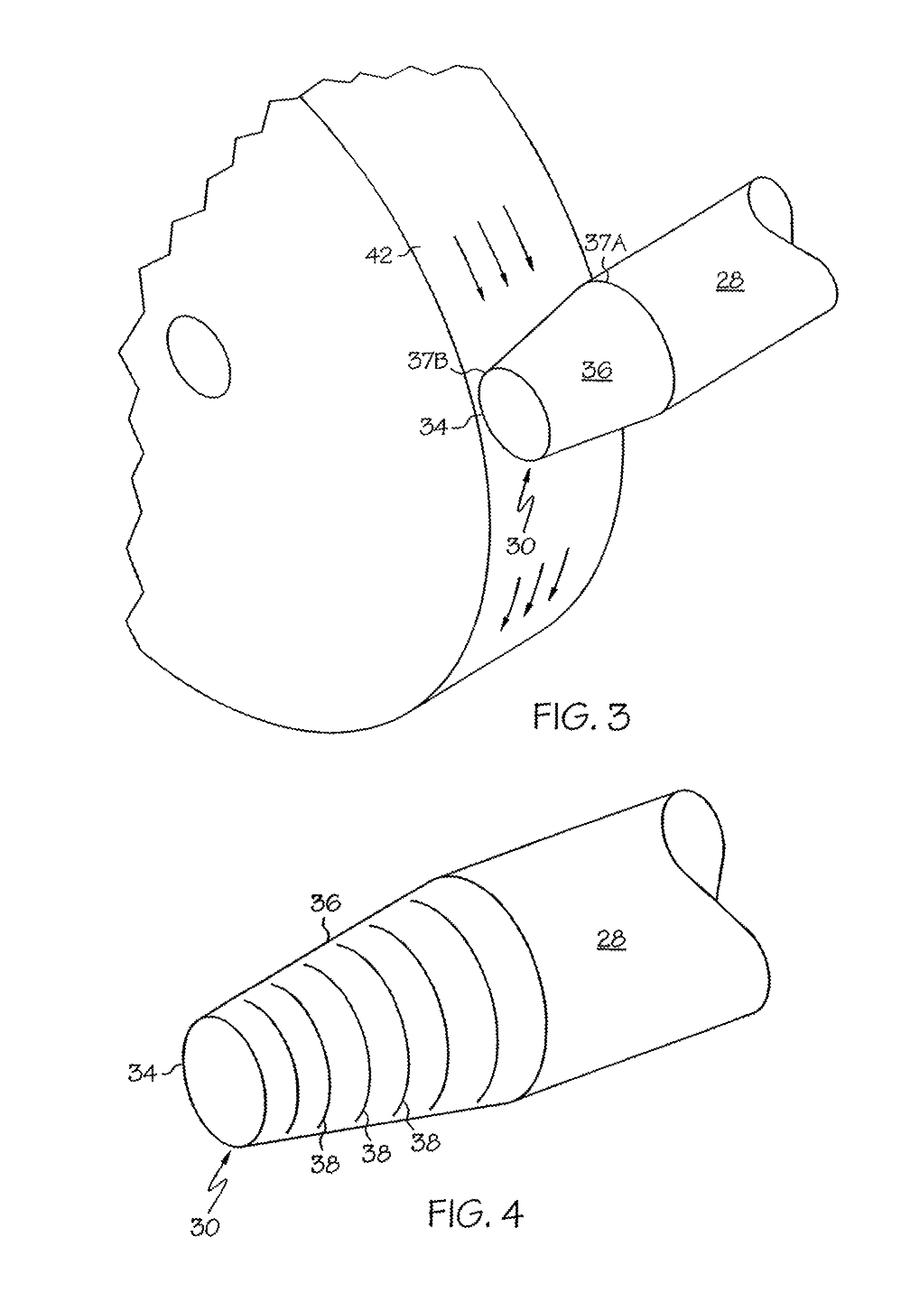
[0038]FIGS. 5A and 5B are side and front views respectively depicting longitudinal grinding of a dispense tip bevel in accordance with the present invention.
[0039]In FIG. 5A, a grind wheel rotates in a clockwise direction, for example at a speed of 3,200 revolutions per minute (RPM). The neck 28 of the dispense tip is presented to the grinding wheel such that the longitudinal axis of the neck substantially aligns with the direction of travel of the grinding wheel. In this manner, a bevel 36 can be formed in a distal end of the neck 28 such that any resulting tooling scars that arise due to the texture of the grinding wheel are substantially longitudinally oriented; in other words, substantially parallel to the longitudinal axis of the dispense tip.
[0040]As seen in the close-up diagram of FIG. 6, a bevel 36 is formed on the dispense tip such that the surface area, or “land” of the tip interface 34 at the opening 32, is substantially reduced. With longitudinal grinding, longitudinal s...
PUM
Abstract
A fluid dispense tip includes a bevel at an opening to reduce the amount of surface tension, or “land”, at the opening. The bevel is formed by grinding in a longitudinal direction such that any tooling scars resulting from the grinding operation are likewise longitudinally oriented, further reducing the amount of surface tension in the tip, thereby leading to heightened dispensing accuracy. The tip may be machined from stock as a unitary piece, to increase its lifetime, and may be formed with a bore of a relatively large diameter that is tapered down to a smaller diameter near the tip opening, to allow for delivery of fluid through the tip body at a decreased pressure. A cleaning tool may be provided for removing residual material from the inner surfaces of the tip. A removable liner sleeve may be provided within the bore to reduce the effective inner diameter of the dispense tip.
Description
RELATED APPLICATIONS[0001]This application is a Continuation of U.S. patent application Ser. No. 11 / 733,517, filed Apr. 10, 2007, which is a Continuation of U.S. patent application Ser. No. 11 / 063,785, filed Feb. 23, 2005, now U.S. Pat. No. 7,207,498, which is a Divisional of U.S. patent application Ser. No. 10 / 304,349, filed Nov. 26, 2002, now U.S. Pat. No. 6,896,202, which is a Divisional of U.S. patent application Ser. No. 09 / 491,615, filed Jan. 26, 2000, now U.S. Pat. No. 6,547,167, which claims the benefit of U.S. Provisional Application No. 60 / 117,201, filed Jan. 26, 1999, and U.S. Provisional Application No. 60 / 163,938, field Nov. 8, 1999, the contents of each being incorporated herein by reference in their entirety.BACKGROUND OF THE INVENTION[0002]Contemporary fluid dispense systems are well suited for dispensing precise amounts of fluid material at precise positions on a substrate. A pump transports the fluid to a dispense tip, also referred to as a “pin” or “needle”, which...
Claims
Application Information
Patent Timeline
Application Date:The date an application was filed.
Publication Date:The date a patent or application was officially published.
First Publication Date:The earliest publication date of a patent with the same application number.
Issue Date:Publication date of the patent grant document.
PCT Entry Date:The Entry date of PCT National Phase.
Estimated Expiry Date:The statutory expiry date of a patent right according to the Patent Law, and it is the longest term of protection that the patent right can achieve without the termination of the patent right due to other reasons(Term extension factor has been taken into account ).
Invalid Date:Actual expiry date is based on effective date or publication date of legal transaction data of invalid patent.