Networked sound masking system

a sound masking and network technology, applied in the field of sound masking, can solve the problems of reducing the comfort level of acoustic perspective, reducing speech privacy, and high noise distraction level

Inactive Publication Date: 2013-07-02
777388 ONTARIO
View PDF15 Cites 147 Cited by
  • Summary
  • Abstract
  • Description
  • Claims
  • Application Information

AI Technical Summary

Benefits of technology

The present invention provides a networked sound masking system with individually controllable and programmable sound masking units for controlling the ambient noise level in a physical environment. This system includes a communication network spanning at least a portion of the physical environment, a plurality of sound masking units, and a control unit for transmitting control signals to the sound masking units to control their operation. The sound masking units include a sound masking component for generating a sound masking output signal and a programmable controller for controlling the operation of the sound masking circuit. Additionally, the system includes a remote control unit for adjusting the characteristics of the sound masking signal output produced by the sound masking units. The technical effects of this invention include the ability to selectively control the operation of sound masking units and adjust their output based on the sound level readings of the physical environment.

Problems solved by technology

Sound masking systems are widely used in offices and similar workplaces where an insufficient level of background sound results in diminished speech privacy.
Such environments suffer from a high level of noise distractions, and lower comfort levels from an acoustic perspective.
The background sound has the effect of limiting the ability to hear two sounds of similar sound pressure level and frequency simultaneously.
Centralized systems are characterized by achieving uniformity of output, but not uniformity of acoustic response for the space.
In practice, it is difficult to accommodate environmental acoustic variations using a centralized system because the volume and frequency spectrum adjustments required for the typical physical zone size are too large to achieve a uniform acoustic result.
A further disadvantage is that many of the adjustments for a centralized sound masking system require an installer or technician to re-enter the ceiling space or to rewire the speakers in the system.
However, with existing systems it is still necessary to re-enter the ceiling to adjust the frequency spectrum and volume output level for each master sound masking unit, and the controls for providing multi-unit volume zone adjustments require the hardwiring of the units.
While existing independent self-contained systems are more flexible than centralized systems in many regards, they do not satisfy all the requirements of an ideal sound masking system as discussed above.
Second, any centrally located controls only affect the output level for the speakers or sound masking units which have a hardwired connection.
It will be appreciated that this severely limits the adjustability of the system to future changes in the acoustic environment unless at least some of the system is rewired.
Third, the tuning procedure for existing systems is time consuming and can still be inaccurate over the system even when undertaken with the appropriate level of skill and attention.

Method used


Image

  • Networked sound masking system
  • Networked sound masking system
  • Networked sound masking system

Examples


Embodiment Construction

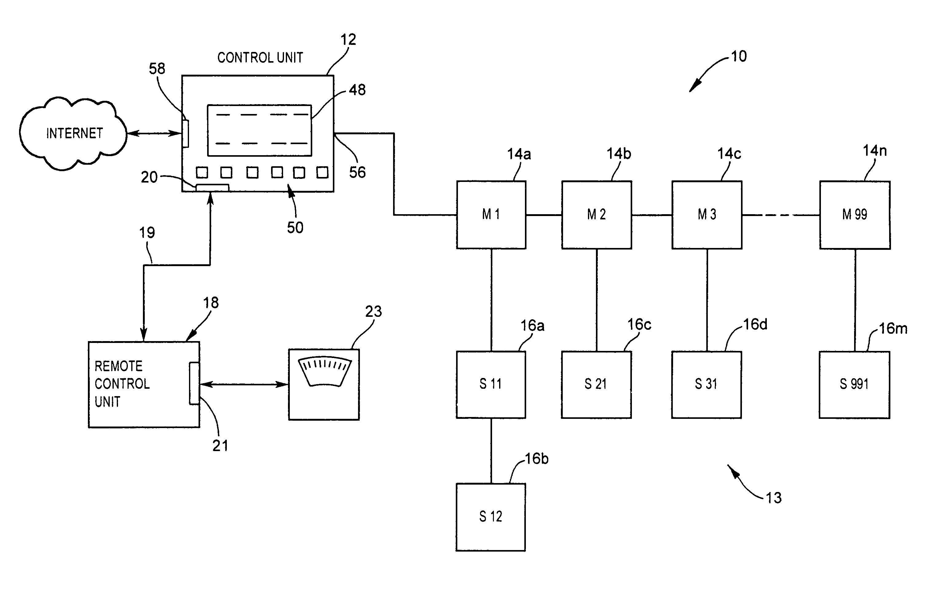
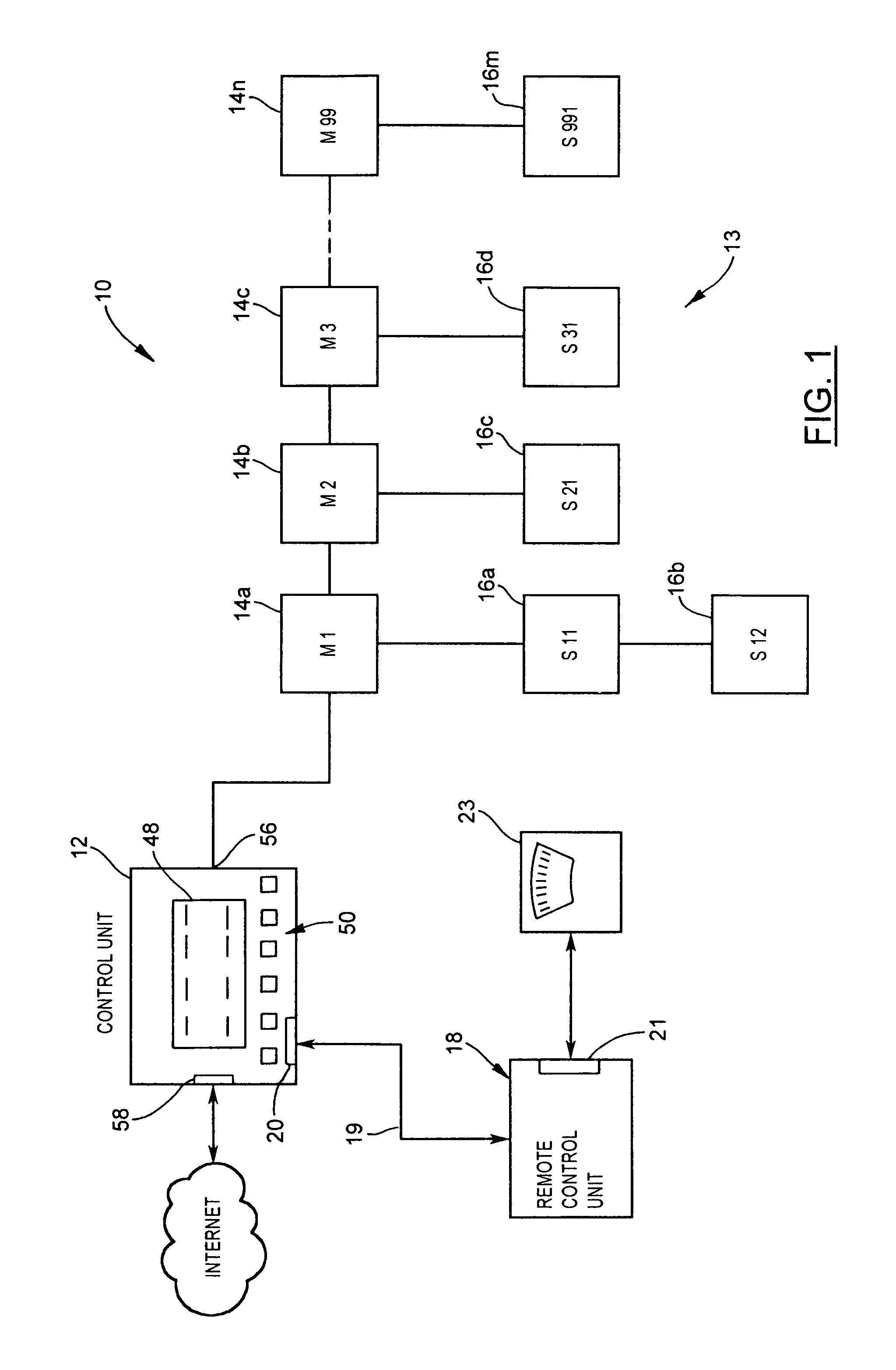
[0033]Reference is first made to FIG. 1, which shows in block diagram form a networked sound masking system according to the present invention and indicated by reference 10.

[0034]As shown in FIG. 1, the networked sound masking system 10 comprises a control unit 12, and a network 13 comprising a plurality of master sound masking units 14, indicated individually by 14a, 14b, 14c . . . 14n, and one or more satellite sound masking units 16, indicated individually by 16a, 16b, 16c, 16d, . . . 16m. The physical connections for the network 13 between the master sound masking units 14 may comprise 5, 4 or 3 conductors. In a 5 conductor arrangement, two conductors carry power, two conductors provide a communication channel, and one conductor provides for paging.

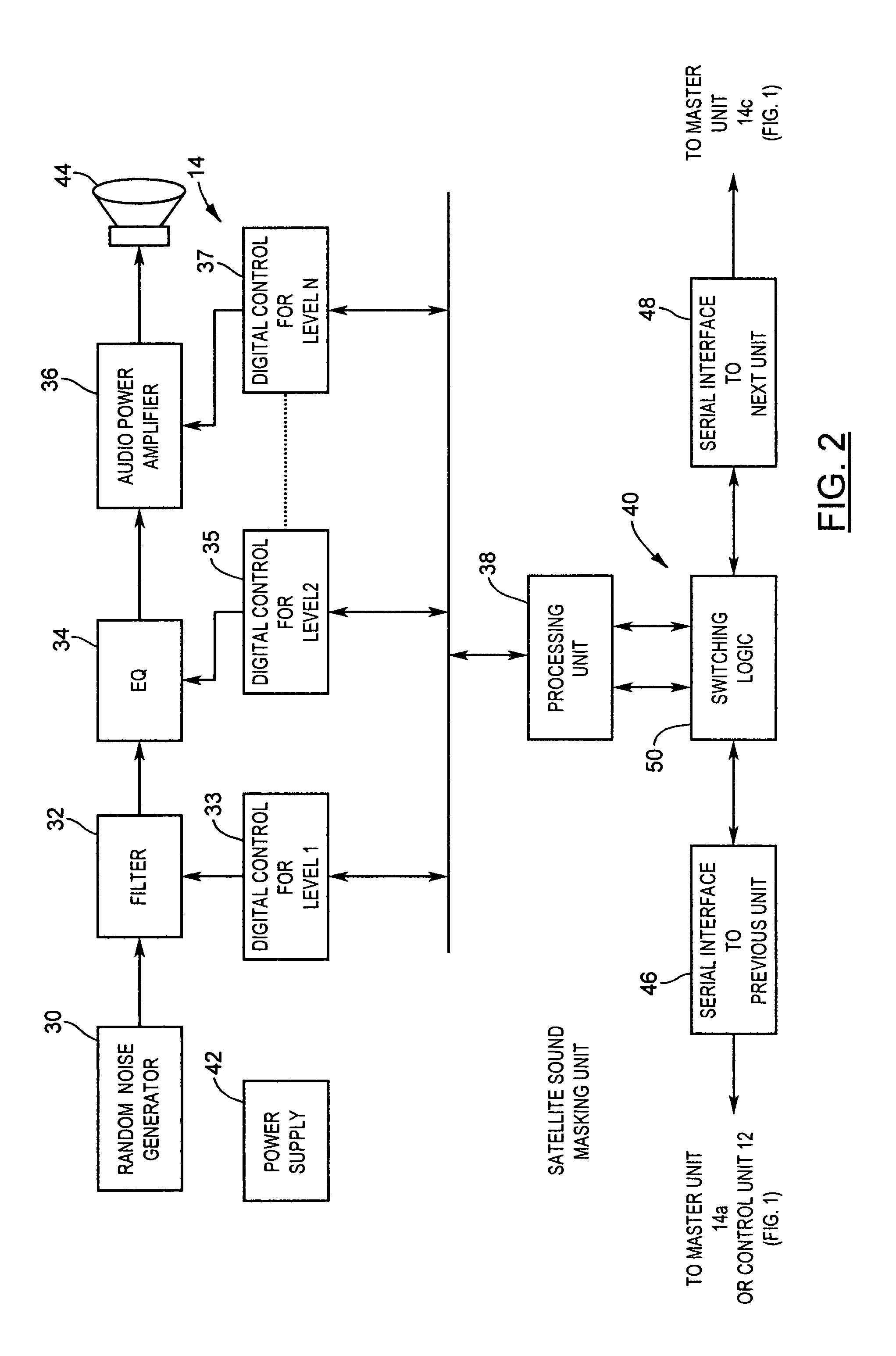
[0035]The master sound masking unit 14 and the satellite sound masking units 16 provide the sound masking functionality, i.e. sound masking and signal generation and amplification. Each sound masking group, i.e. master sound masking u...


PUM


Abstract

A sound masking system for shaping the ambient noise level in a physical environment. The sound masking system comprises a networked and distributed system having a number of master units coupled together and to a control unit. One or more of the master units may include satellite sound masking units which function to reproduce the sound masking signal generated by the master sound masking unit. Each of the master units is addressable over the network by the control unit enabling the control unit to program the contour, spectral band, and gain characteristics of the sound masking output signal. The system may also include a remote control unit which provides the capability to tune and adjust each master sound masking unit in situ without requiring physical access through the ceiling installation.

Description

FIELD OF THE INVENTION[0001]The present invention relates to sound masking, and more particularly to a networked and remote controllable sound masking system.BACKGROUND OF THE INVENTION[0002]Sound masking systems are widely used in offices and similar workplaces where an insufficient level of background sound results in diminished speech privacy. Such environments suffer from a high level of noise distractions, and lower comfort levels from an acoustic perspective. Sound masking systems operate on the principle of masking which involves generating a background sound in a given area. The background sound has the effect of limiting the ability to hear two sounds of similar sound pressure level and frequency simultaneously. By generating and distributing the background noise in the given area, the sound masking system masks or covers the propagation of other sounds in the area and thereby increases speech privacy, reduces the intrusion of unwanted noise, and improves the general acoust...

Claims


Application Information

Patent Timeline
IPC IPC(8): H04R3/02G10K11/175H04M11/02H05K5/02
CPCG10K11/175H04M11/027H04R27/00H04R3/002H05K5/0247G10K11/1752H04K3/42H04K3/43H04K3/45H04K3/825H04K2203/12H04K2203/34G10K2210/3014G10K2210/30351G10K2210/3049
Inventor MOELLER, KLAUS R.MOELLER, NIKLASRUSU, MIRCEADERLA, CARL
Owner 777388 ONTARIO
Why Eureka
Try Eureka