
Adaptive impedance translation circuit

a translation circuit and impedance translation technology, applied in the direction of demodulation, electrical equipment, modulation transference by distributed inductance and capacitance, etc., can solve the problem of large changes in the voltage standing wave ratio (vswr), and achieve the reduction of insertion losses associated with series switching elements, wide impedance adjustment range, and broad range of impedance translation characteristics

Active Publication Date: 2013-06-25
QORVO US INC
View PDF19 Cites 2 Cited by
  • Summary
  • Abstract
  • Description
  • Claims
  • Application Information

AI Technical Summary

Benefits of technology

This patent describes a way to create a circuit that can adjust its impedance over a wide range of frequencies. By combining different circuit topologies and adjusting capacitance, the circuit can work in multiple modes and can be made small and integrated. This technology can minimize signal loss and improve performance.

Problems solved by technology

Such loading changes may cause large changes in a voltage standing wave ratio (VSWR) associated with large impedance changes of the RF antenna.

Method used


Image

  • Adaptive impedance translation circuit
  • Adaptive impedance translation circuit
  • Adaptive impedance translation circuit

Examples


Embodiment Construction

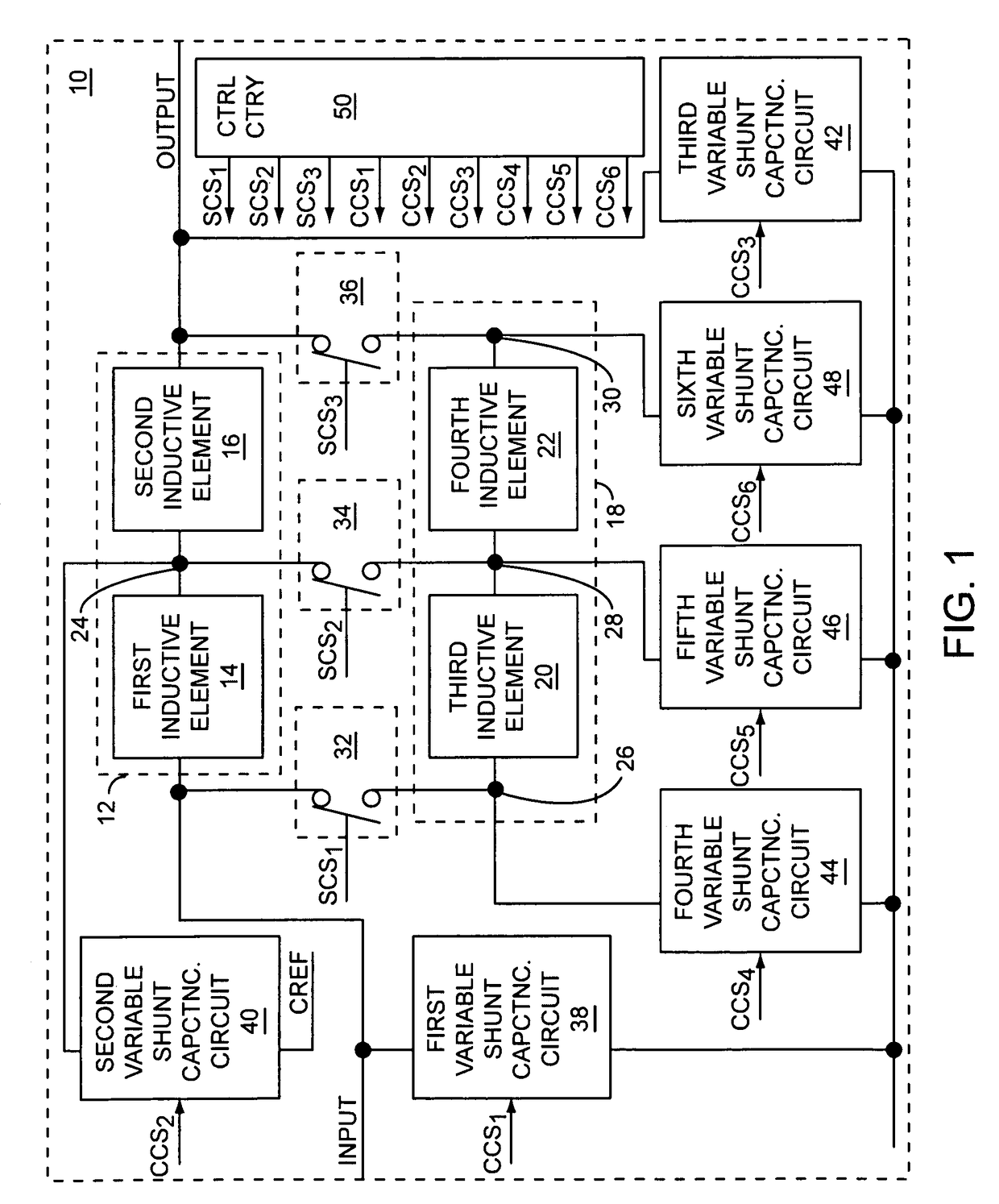
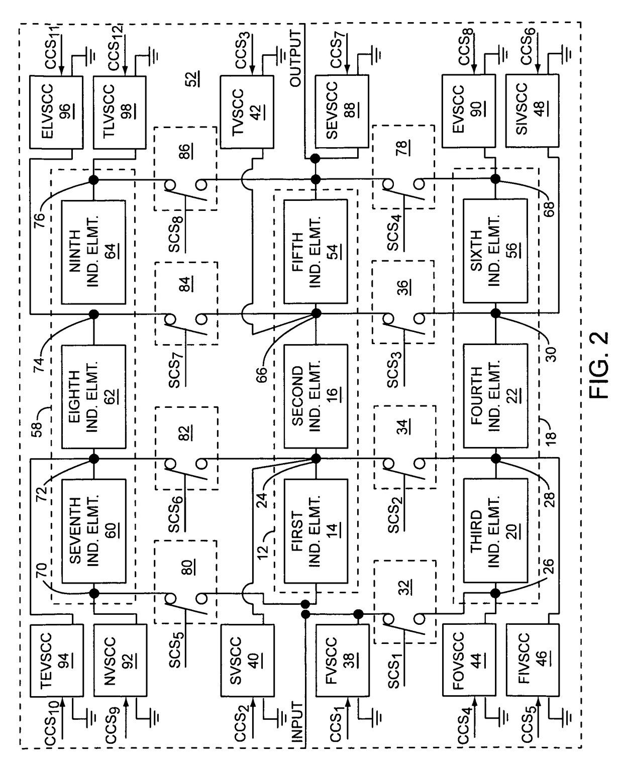
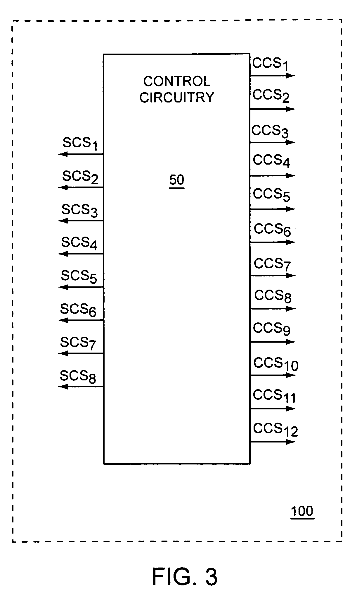
[0006]The present invention relates to an adaptable RF impedance translation circuit that includes a first group of inductive elements cascaded in series between an input and an output without any series switching elements, a second group of inductive elements cascaded in series, and a group of switching elements that are capable of electrically coupling the first group of inductive elements to the second group of inductive elements. Further, the adaptable RF impedance translation circuit includes at least one variable shunt capacitance circuit electrically coupled between a common reference and at least one connection node in the adaptable RF impedance translation circuit, which includes control circuitry to select either an OFF state or an ON state associated with each of the switching elements and to select a capacitance associated with each variable shunt capacitance circuit. By controlling the switching elements and each variable shunt capacitance circuit, the control circuitry...


PUM


Abstract

The present invention relates to an adaptable RF impedance translation circuit that includes a first group of inductive elements cascaded in series between an input and an output without any series switching elements, a second group of inductive elements cascaded in series, and a group of switching elements that are capable of electrically coupling the first group of inductive elements to the second group of inductive elements. Further, the adaptable RF impedance translation circuit includes at least one variable shunt capacitance circuit electrically coupled between a common reference and at least one connection node in the adaptable RF impedance translation circuit, which includes control circuitry to select either an OFF state or an ON state associated with each of the switching elements and to select a capacitance associated with each variable shunt capacitance circuit to control impedance translation characteristics of the adaptable RE impedance translation circuit.

Description

[0001]This application claims the benefit of provisional patent application Ser. No. 61 / 078,108, filed Jul. 3, 2008, the disclosure of which is hereby incorporated herein by reference in its entirety.FIELD OF THE INVENTION[0002]Embodiments of the present invention relate to impedance translation circuits, which may be used in radio frequency (RF) communications systems.BACKGROUND OF THE INVENTION[0003]As wireless communications devices become increasingly ubiquitous, support of multiple communications protocols is often required. As a result, many wireless communications devices are multi-mode devices, which are capable of operating using two or more RF communications bands, which may have frequency ranges that are widely separated from one another, are capable of operating in a half-duplex or a full-duplex operating mode, may operate over a wide range of output power levels, may use multiple modulation techniques, or any combination thereof. To enable high levels of integration, th...

Claims


Application Information

Patent Timeline
Patent Type & Authority Patents(United States)
IPC IPC(8): H04B1/26
CPCH04B1/0458H04B1/18H03D7/161H03D9/06
Inventor FRANCO, MARCELO J.DENING, DAVID C.BAETEN, ROBERT J.
Owner QORVO US INC
Learn More