Method and apparatus for flow parameter imaging

a flow parameter and imaging method technology, applied in the field of ultrasonic imaging, can solve the problems of inability to determine such indices by current color flow imaging techniques, limited frame rate of color flow doppler imaging, and easy observation of flow abnormalities

Active Publication Date: 2013-06-25
GENERAL ELECTRIC CO
View PDF16 Cites 9 Cited by
  • Summary
  • Abstract
  • Description
  • Claims
  • Application Information

AI Technical Summary

Problems solved by technology

Flow abnormalities can be observed easily due to the two-dimensional display of the flow distribution.
Further, the time resolution of color flow Doppler imaging is limited by its frame rate.
Current color flow imaging techniques cannot determine such indices because the time resolution is too poor and the exact spectral shape is unknown.
The disadvantage of spectral Doppler imaging, however, is that the flow parameters are determined at only a single spatial location.
The spatial distribution of the flow parameters is not easily accessible.
However, such an approach is inaccurate, time consuming and expensive, i.e., undesirable.

Method used


Image

  • Method and apparatus for flow parameter imaging
  • Method and apparatus for flow parameter imaging
  • Method and apparatus for flow parameter imaging

Examples


Embodiment Construction

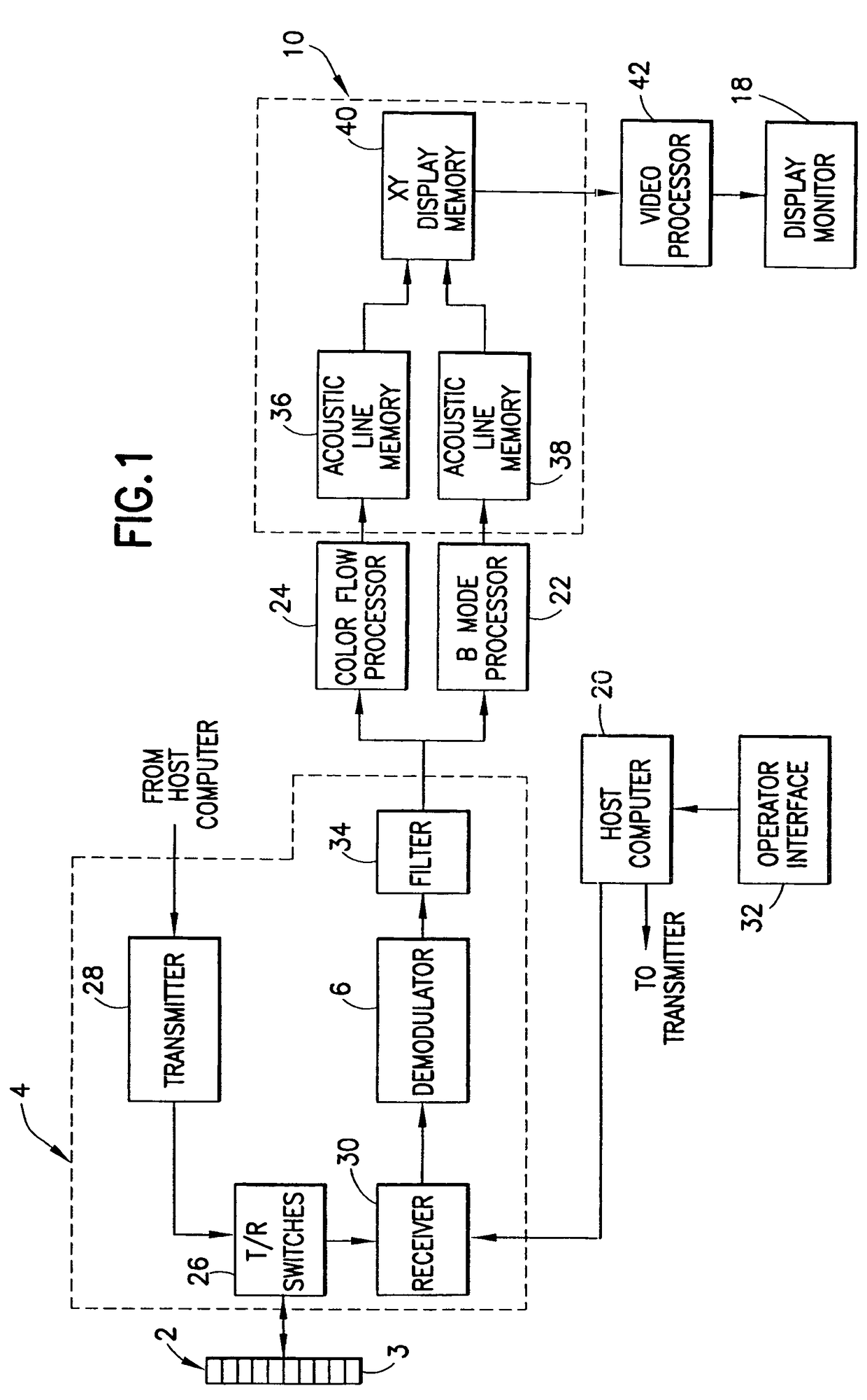
[0028]Referring to FIG. 1, a known ultrasound imaging system comprises a transducer array 2 consisting of a plurality of separately driven transducer elements 3. The transducer is connected to a beamformer 4 comprising a transmitter 28 and a receiver 30. In a transmit mode, a set of transmit / receive (T / R) switches 26 couple the transducer elements to transmitter 28. Each transducer element 3 produces a burst of ultrasonic energy when energized by a respective pulsed waveform produced by transmitter 28. In a receive mode, the T / R switches 26 couple the transducer elements to receiver 30. The ultrasonic energy reflected back to transducer array 2 from the object under study is converted to an analog electrical signal by each receiving transducer element 3 and applied separately to receiver 30. The transmitter and receiver are operated under control of a host computer (i.e., master controller) 20. The host computer 20 determines the conditions under which the acoustic pulses will be tr...


PUM


Abstract

A method and an apparatus for performing pulsed-wave spectral Doppler imaging at every color flow range gate location in a two-dimensional (or three-dimensional) region of interest. Spectral processing is necessary to determine the flow parameters. Performing this processing at every color flow range gate location creates the two-dimensional image. The method generates two-dimensional images of flow parameters such as peak velocity, pulsatility index, resistance index, etc. With the two-dimensional image, the user immediately observes where the most critical value of the flow parameter occurs and what that value is.

Description

BACKGROUND OF THE INVENTION[0001]This invention generally relates to methods and apparatus for ultrasonic imaging of blood flow parameters.[0002]The most common modes of diagnostic ultrasound imaging include B- and M-modes (used to image internal, physical structure), spectral Doppler, and color flow (the latter two primarily used to image flow characteristics, such as in blood vessels). The color flow mode is typically used to detect the velocity of blood flow toward / away from the transducer, and it essentially utilizes the same technique as is used in the spectral Doppler mode. Whereas the spectral Doppler mode displays velocity versus time for a single selected sample volume, color flow mode displays hundreds of adjacent sample volumes simultaneously, all laid over a B-mode image and color-coded to represent each sample volume's velocity.[0003]Measurement of blood flow in the heart and vessels using the Doppler effect is well known. The phase shift of backscattered ultrasound wav...

Claims


Application Information

Patent Timeline
Patent Type & Authority Patents(United States)
IPC IPC(8): A61B8/00A61B8/06
CPCA61B8/06A61B8/488
Inventor HAIDER, BRUNO H.
Owner GENERAL ELECTRIC CO
Why Eureka
Try Eureka