
Display device assembly

a technology of display device and assembly, which is applied in the direction of optical light guide, instruments, optics, etc., can solve the problems of scattering the light which shows up as defects, unsatisfactory, and light falling off in intensity quickly, so as to improve the lighting condition and simplify and effective

Active Publication Date: 2013-06-04
E INK CORPORATION
View PDF70 Cites 38 Cited by
  • Summary
  • Abstract
  • Description
  • Claims
  • Application Information

AI Technical Summary

Benefits of technology

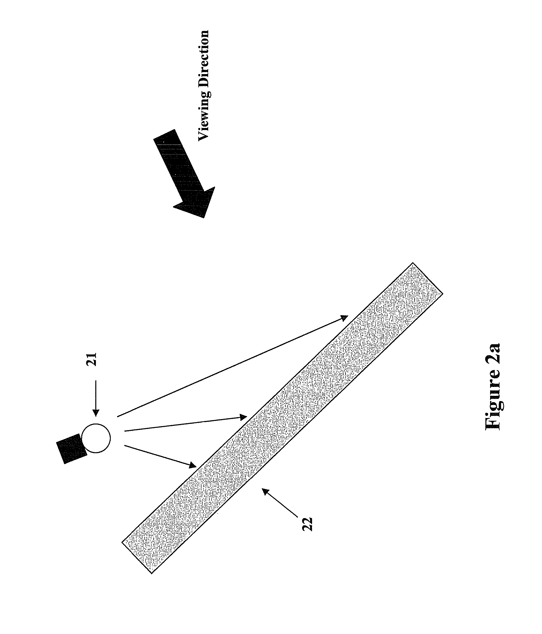
The patent application is about a way to improve the display on a book or e-book by using a small light source from above it. The light source can be a retractable one or a light source that can be folded into a pocket on the book. The improvement is especially noticeable when there is a brighter display on the side that is being viewed.

Problems solved by technology

First, since the light is strongest at the point of entry into the light guide film, the light tends to fall off in intensity rapidly at points which are further from the illuminating source.
Although such a system provides some degree of improvement in lighting uniformity, the uniformity, however, is still unsatisfactory, and the system must be customized for every application.
Secondly, since this lighting system is based on scattering phenomenon, any scratch or piece of dirt in the light guide film also scatters the light which shows up as defects.
As a result, it is very difficult for such a system to function properly.
In addition, if a flexible front light is required, the front light system must be very thin; but a thin front light guide film exacerbates non-uniformity of the light along the length of the light guide film as described above.

Method used


Image

  • Display device assembly
  • Display device assembly
  • Display device assembly

Examples


Embodiment Construction

I. Display Devices

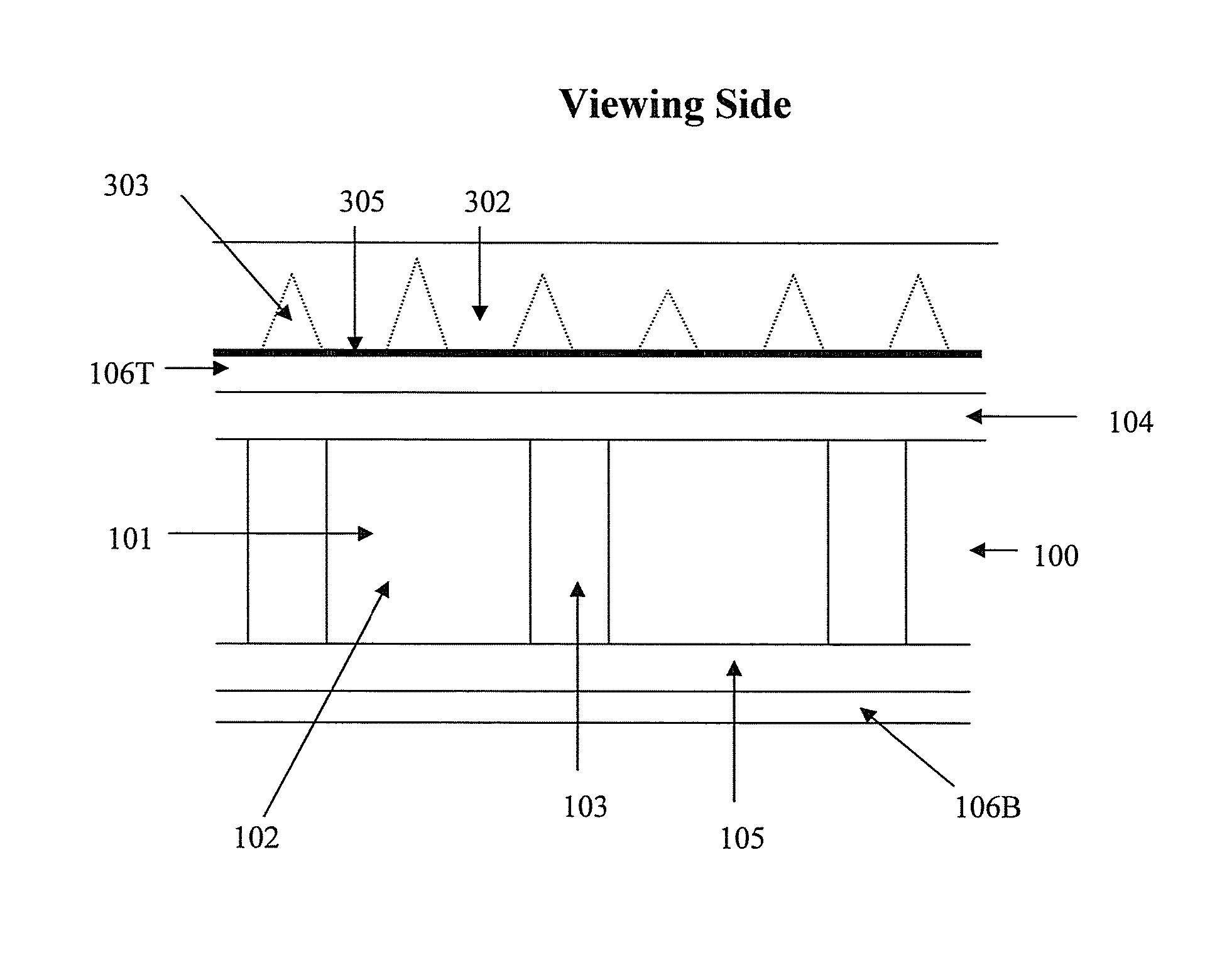
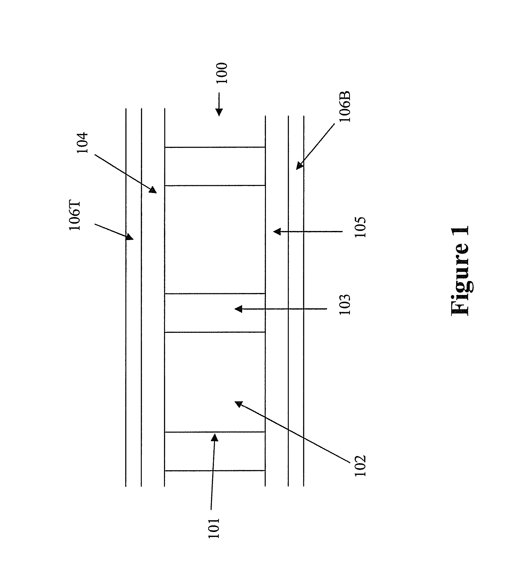
[0030]FIG. 1 illustrates a display device (100). The device comprises display cells (101) which are filled with a display fluid (102) and sandwiched between two electrode layers (104 and 105). Each of the display cells is surrounded by partition walls (103).

[0031]For an electrophoretic display, the display cells are filled with an electrophoretic fluid which comprises charged pigment particles dispersed in a solvent. The display fluid may be a system comprising one or two types of particles.

[0032]In the system comprising only one type of particles, the charged pigment particles are dispersed in a solvent of a contrasting color. The charged particles will be drawn to one of the electrode layers (104 or 105), depending on the potential difference of the two electrode layers, thus causing the display panel to show either the color of the particles or the color of the solvent, on the viewing side.

[0033]In a system comprising particles carrying opposite charges and of t...


PUM

PropertyMeasurementUnit
apex angleaaaaaaaaaa
apex anglesaaaaaaaaaa

Abstract

The present invention is directed to a display device which comprises a display device, a mechanical light and optionally a luminance enhancement structure. This type of display device assembly is particularly useful for e-books comprising a luminance enhancement structure designed to direct a significant amount of light towards the reader of the e-books.

Description

[0001]This application claims priority to U.S. Provisional Application No. 61 / 228,875, filed Jul. 27, 2009; the content of which is incorporated herein by reference in its entirety.FIELD OF THE INVENTION[0002]The present invention is directed to a display device assembly which comprises a display device, a mechanical light and optionally a luminance enhancement structure.BACKGROUND OF THE INVENTION[0003]Reflective displays require a front light system to facilitate viewing of images displayed. The front lighting for reflective displays normally consists of a light guide film attached to the front surface of the display. This light guide film has an illumination source placed at the edge of the light guide film and the light is guided within the film by total internal reflection of the surface along the light guide film, so that the light crosses the front of the display. Part of the surface of the light guide has a light scattering structure which causes light inside the light guide...

Claims


Application Information

Patent Timeline
Patent Type & Authority Patents(United States)
IPC IPC(8): G02F1/1335
CPCG02F1/1336G02B6/0078G02B6/0038G02F2001/133616G02F1/133616
Inventor SPRAGUE, ROBERT A.CHAN, BRYAN HANSLIN, CRAIGPHAM, TINPERI, MANASA
Owner E INK CORPORATION
Learn More