
Techniques for reducing buffer overflow in a communication system

a communication system and buffer overflow technology, applied in the field of communication systems, can solve the problems of reducing the marketplace competitiveness of the ss, and increasing the cost of the ss

Active Publication Date: 2013-04-30
APPLE INC
View PDF27 Cites 0 Cited by
  • Summary
  • Abstract
  • Description
  • Claims
  • Application Information

AI Technical Summary

Benefits of technology

The patent text describes a problem in wireless communication systems where data buffered in a user equipment (SS) can overflow, causing delays and reducing marketplace competitiveness. Various techniques have been attempted to address this problem, such as increasing buffer size and reducing maximum downlink rate, but these techniques have limitations and may not prevent buffer overflow. The present invention provides a solution to reduce buffer overflow in an SS by employing a wide variety of signaling and optimizing resource allocation. The technical effect of this invention is to improve the efficiency and reliability of wireless communication systems by reducing buffer overflow and improving data transmission rates.

Problems solved by technology

Unfortunately, increasing a buffer size of an SS increases a cost of the SS and generally reduces marketplace competitiveness of the SS.
However, reducing a maximum downlink rate of an SS also generally reduces marketplace competitiveness of the SS and limits performance of the SS.
However, reducing buffer overflow occurrences in an SS using conventional flow control may require substantially immediate flow control signaling by the SS upon initial receipt of data (to reduce a data transmission rate of a serving BS).
Unfortunately, flow control signaling by an SS may be subject to delays in obtaining an uplink channel and, as such, any reduction in flow rate attributable to the flow control signaling may not prevent buffer overflow in the SS.

Method used


Image

  • Techniques for reducing buffer overflow in a communication system
  • Techniques for reducing buffer overflow in a communication system
  • Techniques for reducing buffer overflow in a communication system

Examples


Embodiment Construction

[0018]In the following detailed description of exemplary embodiments of the invention, specific exemplary embodiments in which the invention may be practiced are described in sufficient detail to enable those have ordinary skill in the art to practice the invention, and it should be understood that other embodiments may be utilized and that logical, architectural, programmatic, mechanical, electrical and other changes may be made without departing from the spirit or scope of the present invention. The following detailed description is, therefore, not to be taken in a limiting sense, and the scope of the present invention is defined only by the appended claims and their equivalents. In particular, the embodiments described below may be embodied in various wired or wireless communication systems / devices.

[0019]As may be used herein, the term “channel” includes one or more subcarriers, which may be adjacent or distributed across a frequency band. Moreover, the term “channel” may include...


PUM


Abstract

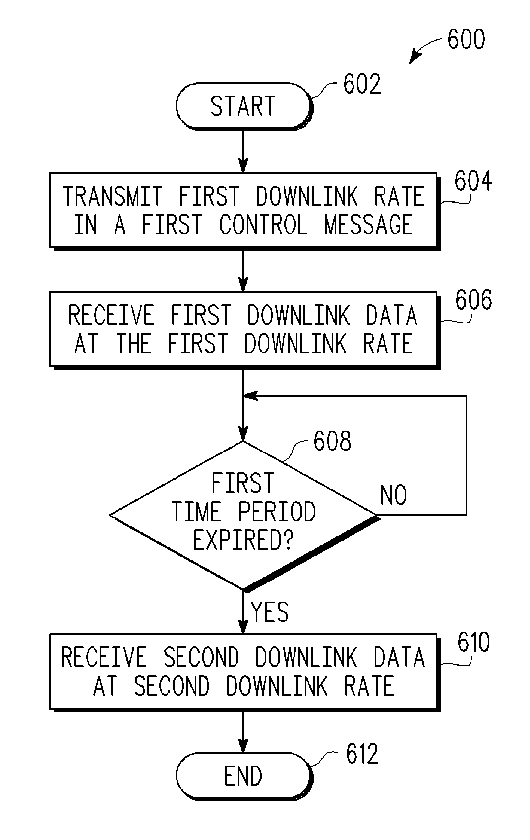
A technique for operating a wireless communication device includes transmitting a first downlink rate in a first control message. The first downlink rate is based on a latency of an inter-processor communication link associated with the wireless communication device. First downlink data at the first downlink rate is then received for a first time period. Following the first time period, second downlink data is received at a second downlink rate that is higher than the first downlink rate.

Description

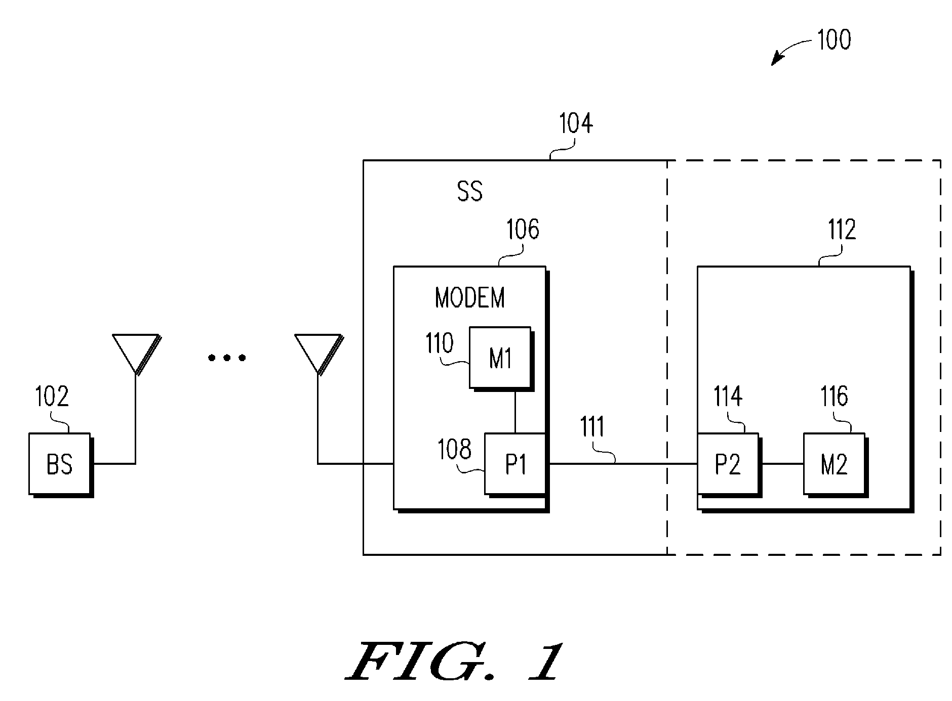
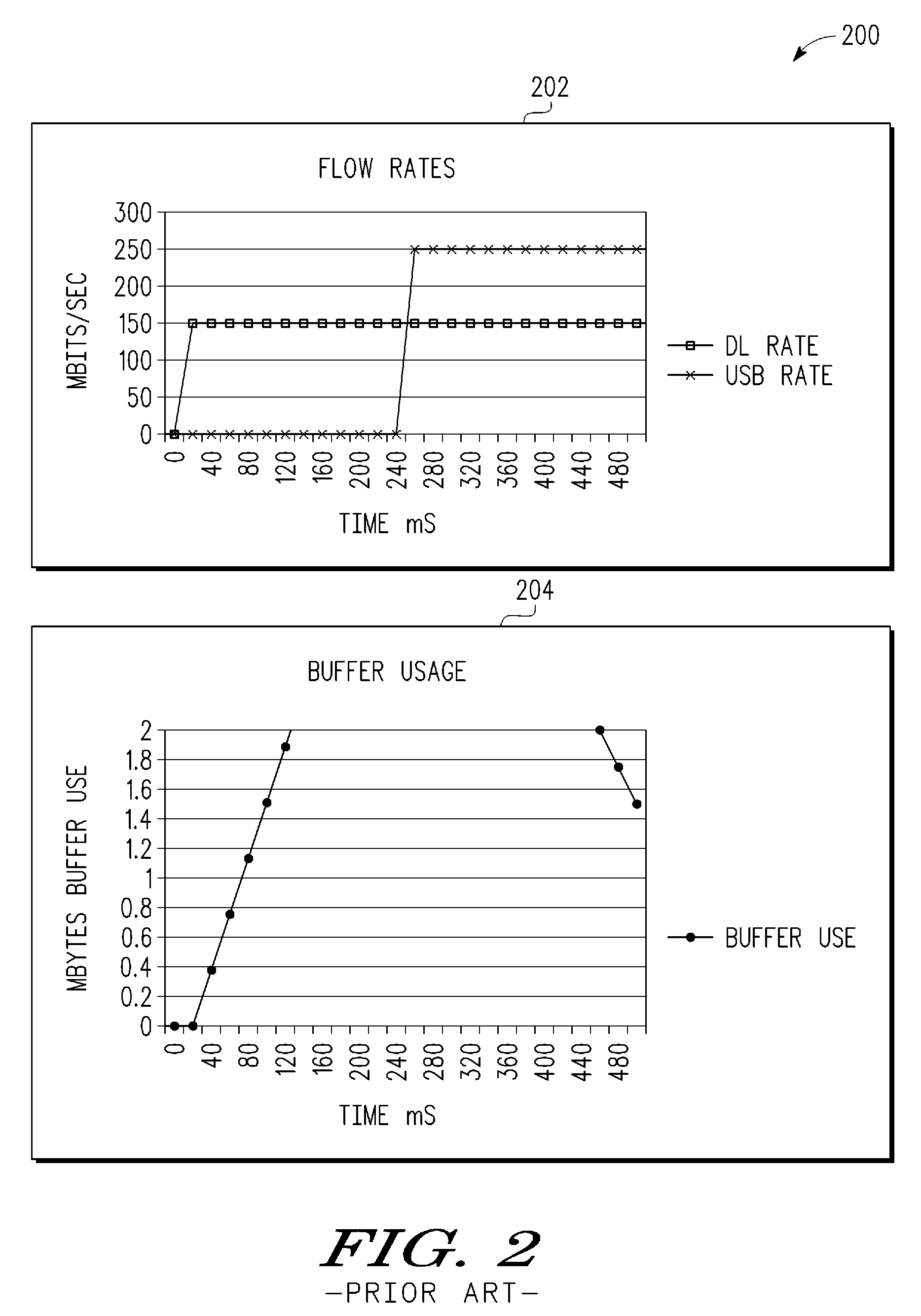
BACKGROUND[0001]1. Field[0002]This disclosure relates generally to a communication system and, more specifically, to techniques for reducing buffer overflow in a communication system.[0003]2. Related Art[0004]In emerging wireless communication systems, such as third generation partnership project long-term evolution (3GPP LTE) systems, downlink rates are generally an order of magnitude faster than legacy wireless communication systems. In a number of different wireless communication systems, data transferred from a serving base station (BS) to user equipment (or a subscriber station (SS)) is buffered in a memory of the SS prior to further processing of the data. In various situations, data stored in a buffer (of an SS) may overflow before further processing of the buffered data is initiated.[0005]A number of different conventional approaches may be employed to reduce buffer overflow occurrences in an SS. For example, a buffer size for an SS may be selected to be a relatively large s...

Claims


Application Information

Patent Timeline
Patent Type & Authority Patents(United States)
IPC IPC(8): H04L12/26H04L47/30
CPCH04L47/10H04L47/14H04L47/263H04W28/10H04L47/30H04W28/14H04L47/283H04W28/22H04W28/0205H04W8/04
Inventor GODFREY, TIM G.
Owner APPLE INC
Learn More