
Apparatus for use in determining a plurality of characteristics of a multiphase flow within a pipe

a multi-phase flow and apparatus technology, applied in the field of flow meters, can solve the problems of inconvenient aggregation of lengths between a dual venturi flow meter and a second type of flow meter, and the inability to accommodate both a dual venturi flow meter and a water cut flow meter within a subsea christmas tr

Active Publication Date: 2013-04-30
BAKER HUGHES INC
View PDF19 Cites 18 Cited by
  • Summary
  • Abstract
  • Description
  • Claims
  • Application Information

AI Technical Summary

Benefits of technology

The patent describes an apparatus to measure multiple characteristics of a flow in a pipe. It includes two constrictions, a sheltered area in between, and two sensing devices that measure the flow in that area. The first characteristic is measured by the sensing device, while the second characteristic is measured by the sheltered device. This design allows for accurate measurements of each characteristic based on the data collected from the two devices.

Problems solved by technology

The aggregate lengths of a dual venturi flow meter and a second type of flow meter can be prohibitive of their collective serial installation within a subsea Christmas tree, which is an assembly of valves, spools, and fittings used to control the flow into or out of a subsea well, such as an oil well or a gas well.
In a practical use case scenario, after the gas fraction and the liquid fraction are determined using a dual venturi flow meter, it may be desirious to determine a liquid composition of the multiphase flow using a water cut flow meter.
However, the amount of space within a subsea Christmas tree may not accommodate both a dual venturi flow meter and a water cut flow meter for use in determining each of the gas fraction, the liquid fraction, and the liquid composition.

Method used


Image

  • Apparatus for use in determining a plurality of characteristics of a multiphase flow within a pipe
  • Apparatus for use in determining a plurality of characteristics of a multiphase flow within a pipe
  • Apparatus for use in determining a plurality of characteristics of a multiphase flow within a pipe

Examples


Embodiment Construction

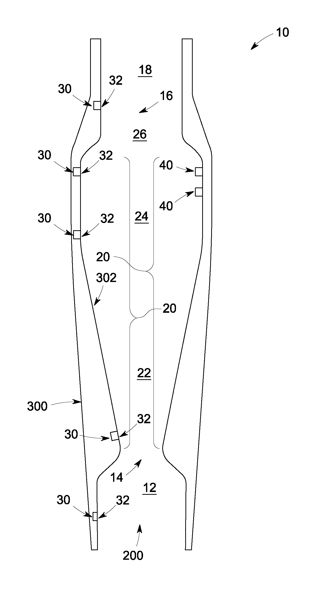
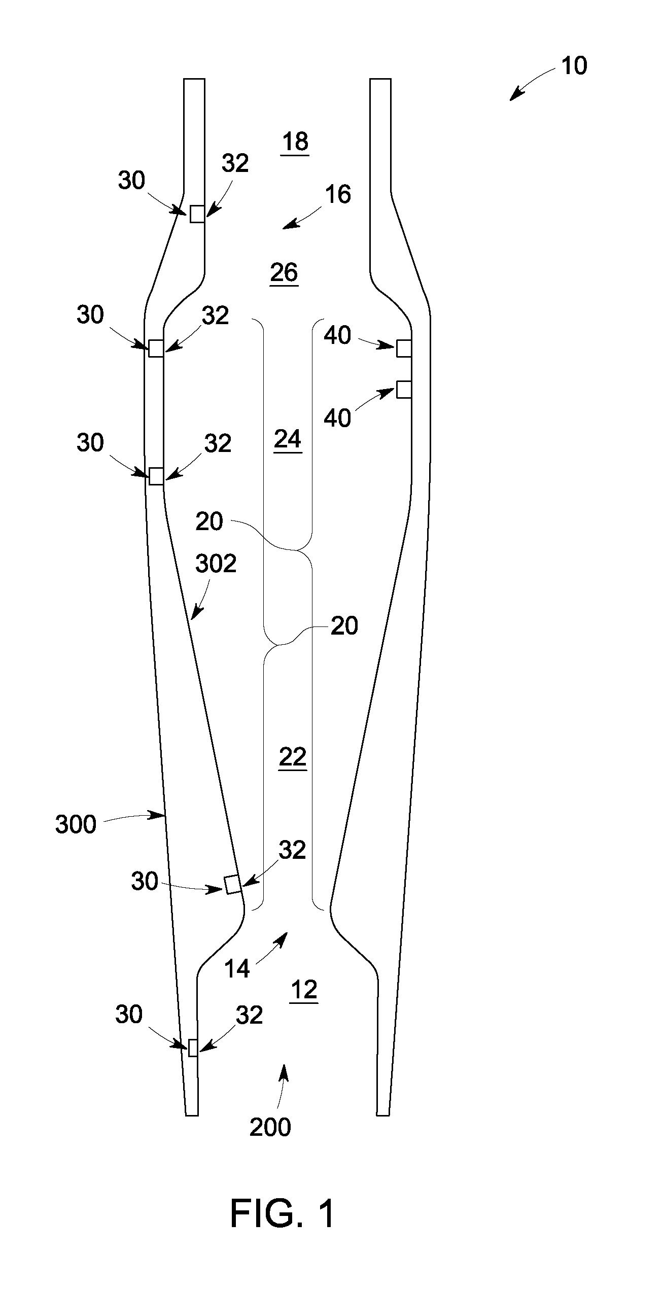
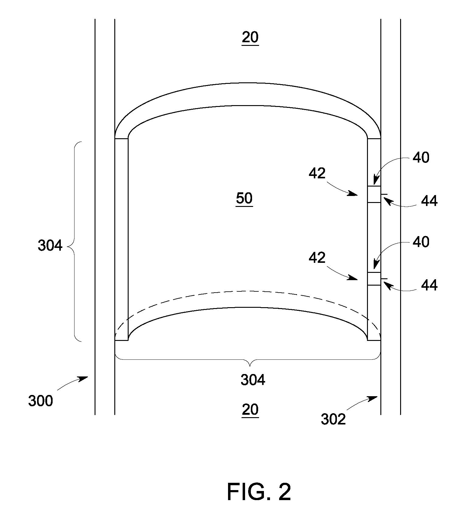
[0014]FIG. 1 is a cross-sectional side view of an apparatus 10 according to one exemplary embodiment of the invention. Apparatus 10 can be used for determining a plurality of characteristics 100 (shown in FIG. 6) of a multiphase flow 200 within a pipe 300. Apparatus 10 can comprise a first cylindrical section 12 leading into a first constriction 14, a second constriction 16 leading into a second cylindrical section 18, a sheltered zone 20 between first constriction 14 and second constriction 16, a sensing device 30 coupled to an interior wall 302 of pipe 300, and a sheltered device 40 coupled to interior wall 302 and located within sheltered zone 20. First constriction 14 and second constriction 16 can cause a Venturi effect on multiphase flow 200. A Venturi effect is a reduction in fluid pressure that results when a fluid flows through a constricted section of a pipe. The difference in pressure of the fluid before the constriction and at the constriction (a “differential pressure” ...


PUM


Abstract

An apparatus for use in determining a plurality of characteristics of a multiphase flow within a pipe is disclosed. In one exemplary embodiment, the apparatus comprises first and second constrictions, a sheltered zone between the first and second constrictions, a sensing device coupled to an interior wall of the pipe, and a sheltered device coupled to the interior wall of the pipe and located within the sheltered zone. A first characteristic of the plurality of characteristics is determinable from data generated by the sensing device. A second characteristic of the plurality of characteristics is determinable from data generated by the sheltered device. In one exemplary embodiment, the first characteristic is a gas fraction, and the sensing device is a plurality of pressure sensors. In another exemplary embodiment, the second characteristic is a phase fraction, and the sheltered device is a plurality of electrical impedance spectroscopy (EIS) electrodes.

Description

BACKGROUND OF THE INVENTION[0001]The subject matter herein relates generally to flow meters and, more particularly, to an improved flow meter for use in determining a plurality of characteristics of a flow comprising more than one phase of matter such as liquid and gas (a “multiphase flow”) within a pipe.[0002]Flow meters provide critical measurements concerning the characteristics of a multiphase flow within a pipe. For example, in the oil industry, there are various situations in which there is a need to use a flow meter to determine a fraction of the gas phase (the “gas fraction”) and a fraction of the liquid phase (the “liquid fraction”) comprising the multiphase flow. A dual venturi flow meter can be used for this purpose. In a typical dual venturi flow meter, there are two constrictions, each being formed by a separate constricting conical section and a separate expanding conical section. Differences in pressure of the multiphase flow across the constrictions bear an empirical...

Claims


Application Information

Patent Timeline
Patent Type & Authority Patents(United States)
IPC IPC(8): G01F1/74G01F1/44G01F1/37
CPCG01F1/363G01F1/44G01F1/66G01F1/74G01F1/88
Inventor FURLONG, EDWARD RANDALL
Owner BAKER HUGHES INC
Learn More