
Image display apparatus and method of controlling the same

a technology of image display and apparatus, applied in the direction of instruments, optics, static indicating devices, etc., can solve the problems of temperature unevenness, image distortion, joint noticeable, etc., and achieve the effect of reducing temperature unevenness

Active Publication Date: 2013-04-09
CANON KK
View PDF11 Cites 4 Cited by
  • Summary
  • Abstract
  • Description
  • Claims
  • Application Information

AI Technical Summary

Benefits of technology

The present invention is about an image display that reduces temperature unevenness on a reflection surface by displaying an image based on a light beam reflected by the surface that makes a reciprocating rotation. This results in a more uniform display of the image.

Problems solved by technology

Japanese Patent Laid-Open No. 2006-220745 presents a problem in a micromirror scanner using the resonance phenomenon of a silicon substrate.
The temperature unevenness appears as image distortion.
This causes a scan shift at the overlap portion of the left and right video images and consequently makes the joint noticeable.

Method used


Image

  • Image display apparatus and method of controlling the same
  • Image display apparatus and method of controlling the same
  • Image display apparatus and method of controlling the same

Examples


ninth embodiment

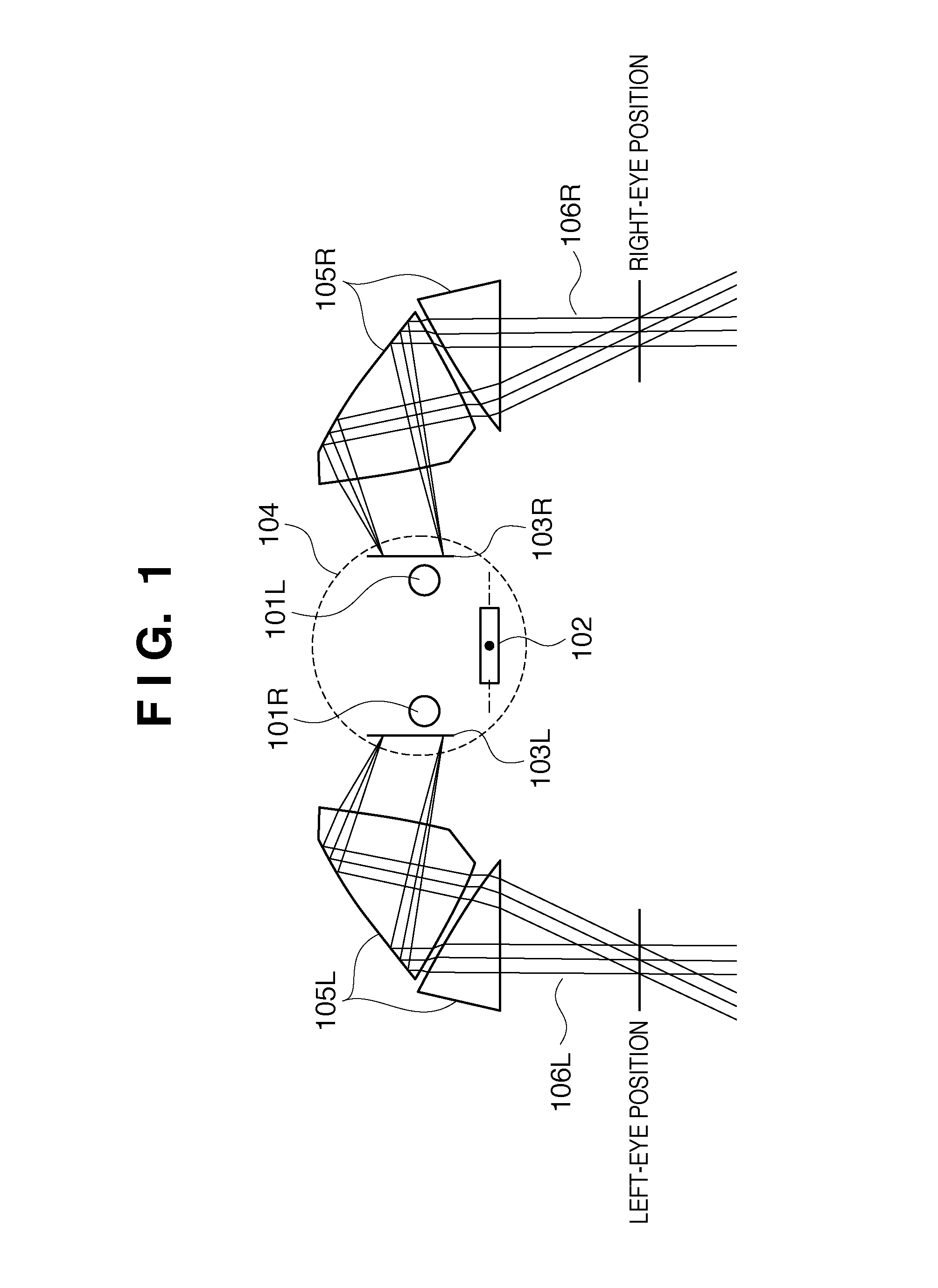
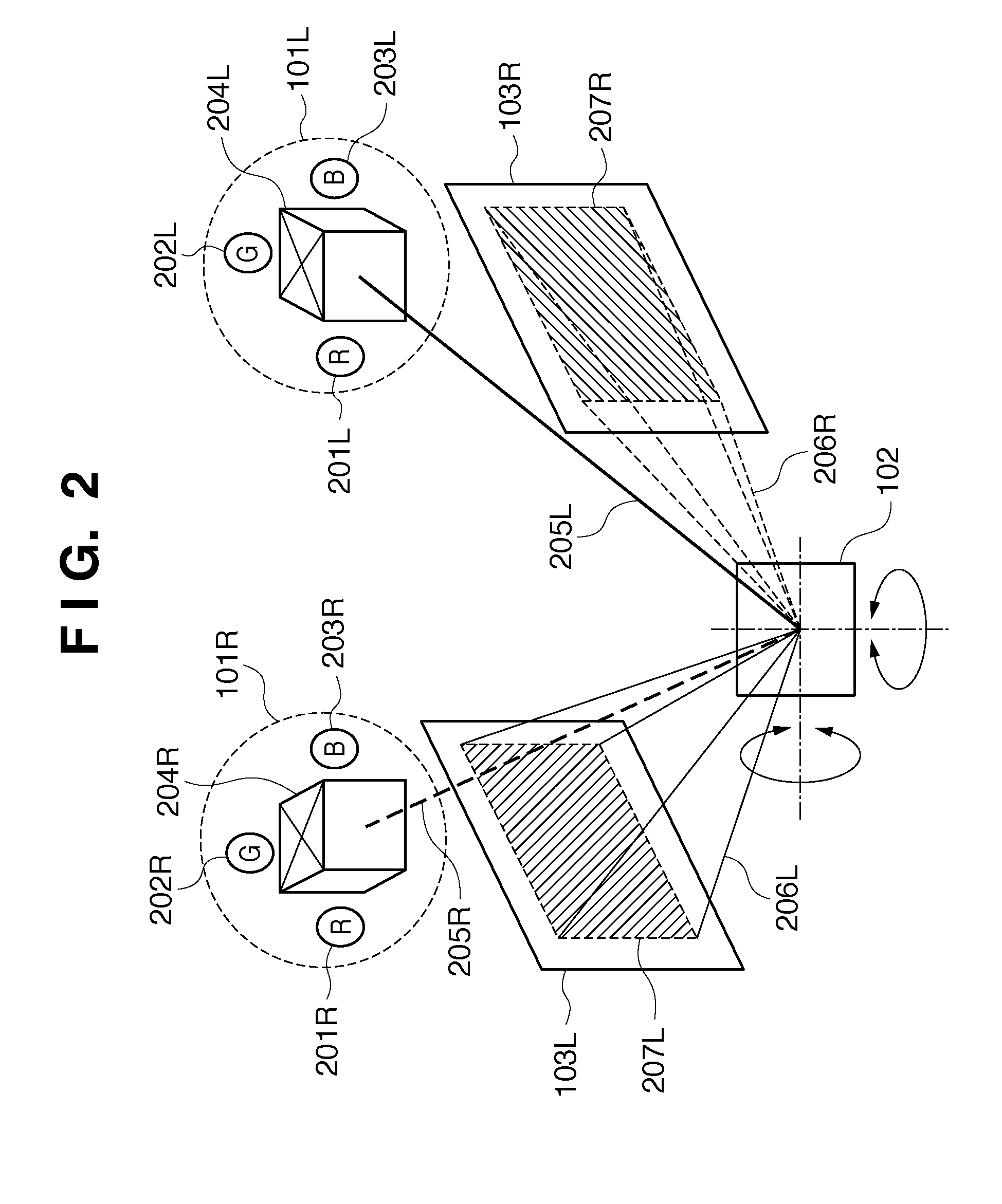
[0214]The ninth embodiment will be described next. In the ninth embodiment, an arrangement that combines the display form using division in the vertical direction described in the sixth embodiment with the display form using division in the horizontal direction described in the eighth embodiment will be explained. Hence, a video image generation unit according to the ninth embodiment has an arrangement formed by combining the eighth embodiment (FIG. 30) and the sixth embodiment (FIG. 21). The light source driving timing of horizontal scanning of the ninth embodiment is the same as in the eighth embodiment (FIG. 31). The light source driving timing of vertical scanning of the ninth embodiment uses the processing of the sixth embodiment (FIG. 22). Scan positions at the respective horizontal scanning timings of the ninth embodiment are the same as in the eighth embodiment (FIG. 32). Scan positions at the respective vertical scanning timings are the same as in the sixth embodiment (FIG....


PUM


Abstract

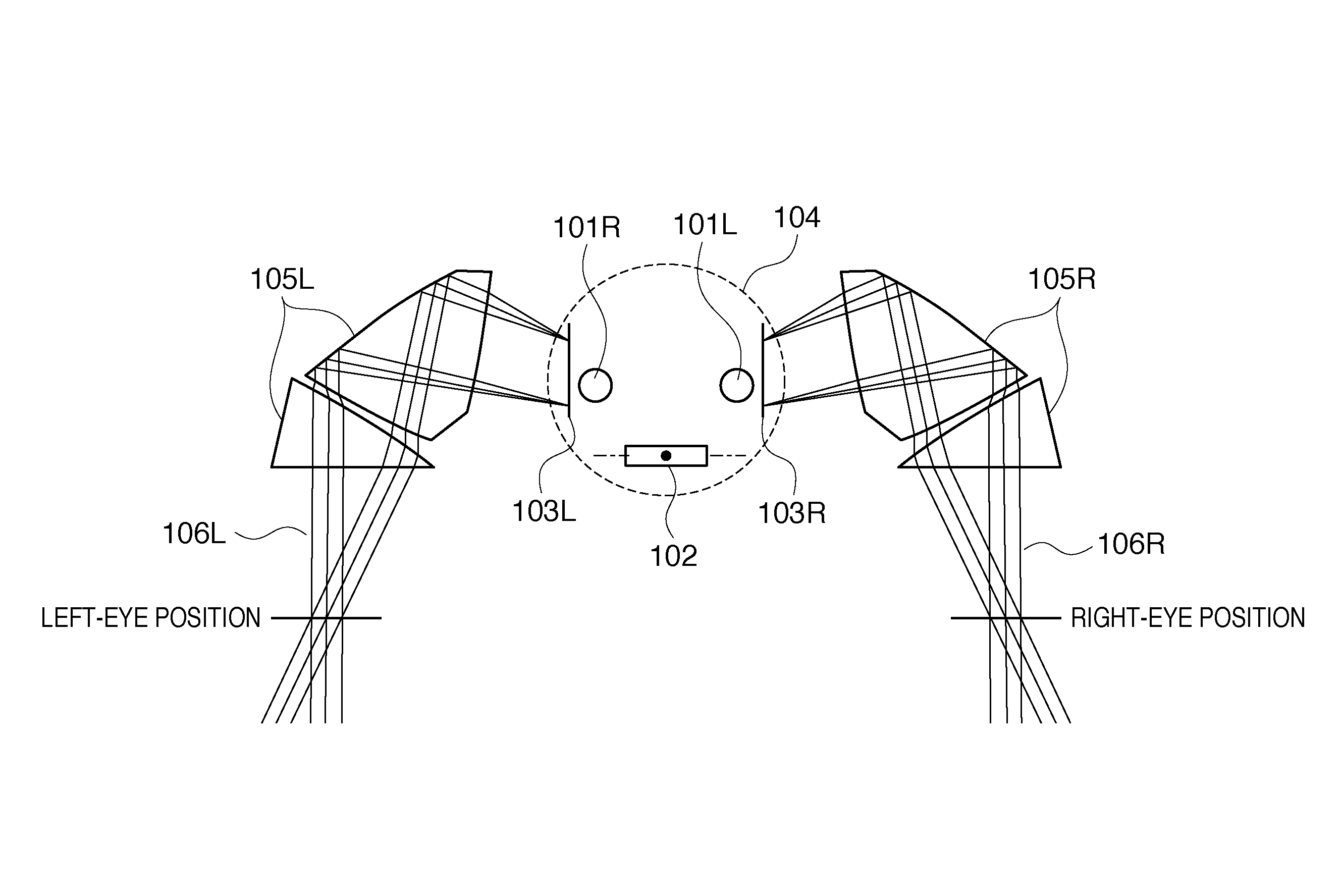
An image display apparatus generates a first light beam and a second light beam corresponding to image signals for the eyes of an observer, and makes the first light beam and the second light beam incident on a reflection surface which makes a reciprocating rotation about a first axis, thereby generating first and second scanning light beams to scan in a lateral direction. Images observable by the eyes of the observer are formed based on the first and second scanning light beams. Control is performed to reflect the first light beam and generate the first scanning light beam while the reflection surface rotates in the first direction of the reciprocating rotation and reflect the second light beam and generate the second scanning light beam while the reflection surface rotates in the second direction opposite to the first direction.

Description

BACKGROUND OF THE INVENTION[0001]1. Field of the Invention[0002]The present invention relates to an apparatus for displaying a video image and, more particularly, to a head-mounted image display apparatus (head-mounted display), a hand-held image display apparatus (hand-held display), and an image projecting apparatus.[0003]2. Description of the Related Art[0004]There have conventionally been proposed head-mounted image display apparatuses (head-mounted displays) and hand-held image display apparatuses (hand-held displays) which guide image light to the pupils of an observer and displays a virtual image. Japanese Patent Laid-Open No. 11-95144 proposes an image display apparatus for displaying an image based on a light beam reflected by a reflection surface that makes a reciprocating rotation.[0005]The image display apparatus described in Japanese Patent Laid-Open No. 11-95144 includes one horizontal scanning unit (shared by left and right eyes) and two vertical scanning units. The h...

Claims


Application Information

Patent Timeline
Patent Type & Authority Patents(United States)
IPC IPC(8): G02B27/14G09G5/00
CPCG02B26/101G02B27/017G02B30/35G02B2027/011G02B2027/014
Inventor NAKANISHI, HIROYUKI
Owner CANON KK
Learn More