Transverse flux induction heating device
a technology of induction heating and transverse flux, which is applied in the direction of electric/magnetic/electromagnetic heating, heat treatment apparatus, furnaces, etc., can solve the problems of both ends in the width direction (both side ends) of the conductive sheet of the heating target becoming overheated, and achieve the uneven temperature distribution in the width direction of the conductive sheet of the heating target, the effect of reducing the uneven temperature distribution and reliability flow of eddy curren
- Summary
- Abstract
- Description
- Claims
- Application Information
AI Technical Summary
Benefits of technology
Problems solved by technology
Method used
Image

Examples
first embodiment
[0075]First, the first embodiment will be described.
[0076][Configuration of Continuous Annealing Line]
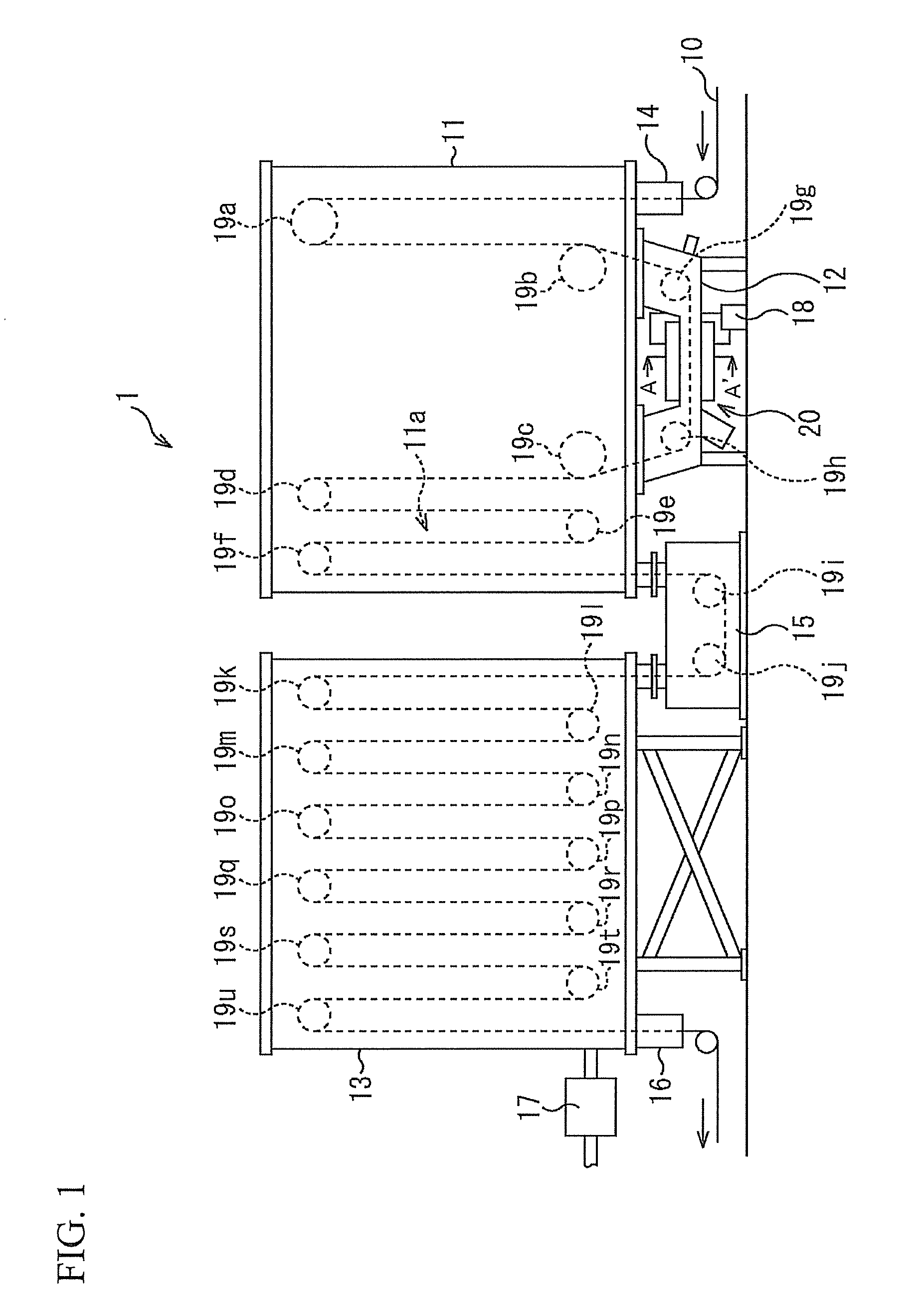
[0077]FIG. 1 is a side view showing one example of the schematic configuration of a continuous annealing line for a steel sheet. In addition, in each drawing, for convenience of explanation, only the necessary configuration is simplified and shown.
[0078]In FIG. 1, a continuous annealing line 1 includes a first container 11, a second container 12, a third container 13, a first sealing roller assembly 14, a conveyance unit 15, a second sealing roller assembly 16, a gas supply unit 17, an alternating-current power supply unit 18, rollers 19a to 19u (19), and an induction heating device 20.
[0079]The first sealing roller assembly 14 transports a steel strip (a strip-shaped sheet) 10 into the first container 11 while shielding the first container 11 from the external air. The steel strip 10 conveyed into the first container 11 by the first sealing roller assembly 14 is conveyed into the s...
second embodiment
[0157]Next, the second embodiment of the present invention will be described. In the first embodiment, nothing is housed in the depressed portion of the shielding plate (only air is contained in the depressed portion of the shielding plate). In contrast, in this embodiment, a non-conductive soft magnetic material is housed in the depressed portion of the shielding plate. In this manner, this embodiment is mainly different from the first embodiment in that the non-conductive soft magnetic material is housed in the depressed portion of the shielding plate. Therefore, in the description of this embodiment, the same portion as that in the first embodiment is denoted by the same symbol as the symbol used in FIGS. 1 to 5D and a detailed explanation is omitted.
[0158]FIGS. 6A to 6D are diagrams showing one example of the configuration of the shielding plate.
[0159]Specifically, FIG. 6A is a top view of a shielding plate 101 when viewed from directly above (the steel strip 10 side). Further, ...
example
[0172]FIG. 7 is a diagram showing one example of the relationship between the amount of insertion of the shielding plate and a width temperature deviation ratio.
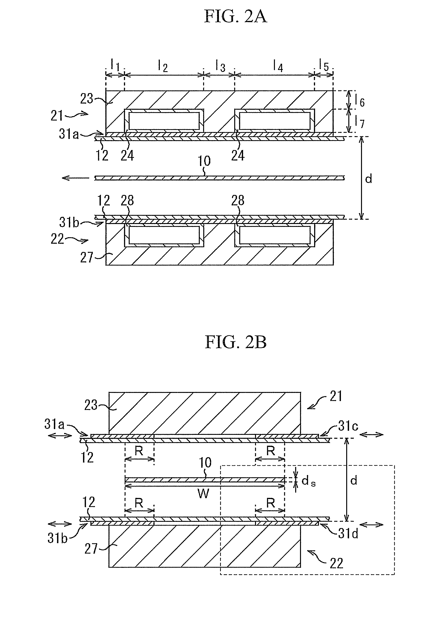
[0173]The amount of insertion of the shielding plate corresponds to the “overlap length R in the width direction of the steel strip 10” between each of both side end portions of the steel strip 10 and each shielding plate (refer to FIG. 2B). Further, the width temperature deviation ratio is a value (=sheet width central portion temperature / sheet end portion temperature) obtained by dividing the temperature of the central portion in a temperature distribution in the width direction of the steel strip 10 (the sheet width central portion temperature) by the temperature of the end portion (the sheet end portion temperature).
[0174]In FIG. 7, in a graph A1, a plain shielding plate in which no depressed portion is formed was used. In a graph A2, a shielding plate in which brimmed depressed portions are formed, as in the first embod...
PUM
| Property | Measurement | Unit |
|---|---|---|
| thickness | aaaaa | aaaaa |
| thickness | aaaaa | aaaaa |
| width | aaaaa | aaaaa |
Abstract
Description
Claims
Application Information
 - R&D
- Intellectual Property
- Life Sciences
- Materials
- Tech Scout
- Unparalleled Data Quality
- Higher Quality Content
- 60% Fewer Hallucinations
Browse by: Latest US Patents, China's latest patents, Technical Efficacy Thesaurus, Application Domain, Technology Topic, Popular Technical Reports.
© 2025 PatSnap. All rights reserved.Legal|Privacy policy|Modern Slavery Act Transparency Statement|Sitemap|About US| Contact US: help@patsnap.com