Wire rod cooling device and wire rod cooling method

A technology of cooling device and cooling method, which is applied in the direction of workpiece cooling device, cooling bed, quenching device, etc., can solve the problems of unfixed ring spacing, irregular overlapping method of wire rods, irregular overlapping method, etc., and eliminate the decline in yield , Reduce the effect of temperature unevenness

Inactive Publication Date: 2016-06-08
NIPPON STEEL CORP
View PDF14 Cites 4 Cited by
  • Summary
  • Abstract
  • Description
  • Claims
  • Application Information

AI Technical Summary

Problems solved by technology

[0011] In addition, since the ring spacing is not fixed, the wires overlap each other in an irregular manner
E.g figure 1 As shown, it can be seen that there is no regularity in the overlapping manner of the wire rod M on the straight line L along the conveying direction T.

Method used


Image

  • Wire rod cooling device and wire rod cooling method
  • Wire rod cooling device and wire rod cooling method
  • Wire rod cooling device and wire rod cooling method

Examples


Embodiment Construction

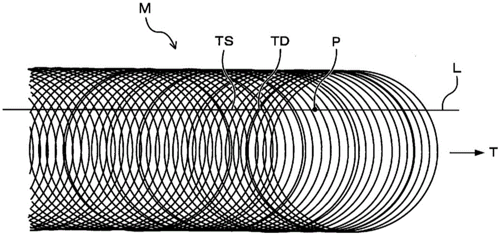
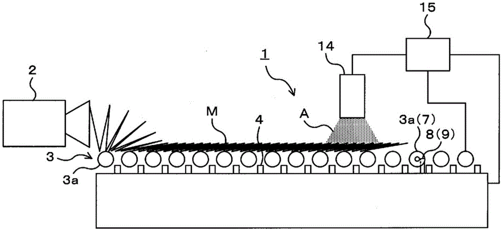
[0052] Next, an embodiment of the present invention will be described based on the wire rod cooling device 1 that cools the non-concentric ring-shaped wire M coiled by the wire laying machine 2 (wire coiler). In addition, in the present embodiment, the conveying speed of the endless wire material M by the roller conveyor 3 provided on the exit side of the wire laying machine 2 is constant. In addition, in the present embodiment, compressed air is used as the refrigerant for cooling the annular wire material M. FIG. As the refrigerant of the conventional Stelmore cooling, air sent by a blower is used. In addition, in this specification and drawings, the same code|symbol is attached|subjected to the element which has substantially the same functional structure, and repeated description is abbreviate|omitted.

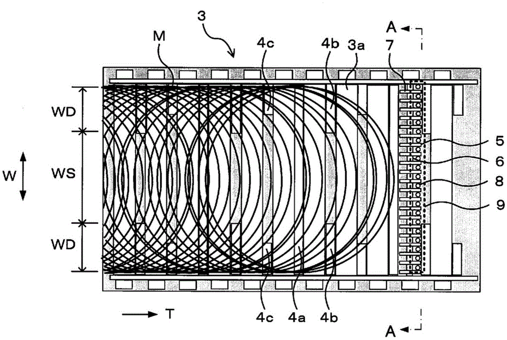
[0053] Such as figure 2 , image 3 As shown, in the wire rod cooling device 1 , the slit nozzle 4 is provided between the rollers 3 a of the roller conveyor 3 . Each ...


PUM


Abstract

A wire rod cooling device for cooling a wire rod wound in a ring shape by a wire rod winder while conveying the wire rod on a conveyor is provided with: a plurality of jet nozzles which are disposed along the width direction of the conveyor and each jet a refrigerant toward the wire rod; an image capturing unit which is provided on the conveyance line upstream side of a jet nozzle row composed of the plurality of jet nozzles and captures an image of the wire rod that is being conveyed; and a control unit which extracts density information and temperature information relating to the wire rod from the captured image. On the basis of the density information and temperature information relating to the wire rod, the control unit controls the flow rate of the refrigerant to be jetted from each of the jet nozzles with respect to each of the jet nozzles in accordance with a timing when a specific portion corresponding to the information arrives at the jet nozzle.

Description

technical field [0001] The present invention relates to a wire rod cooling device and a wire rod cooling method for adjusting and cooling the wire rod conveyed by a conveyor after coiling the wire rod formed by hot rolling of a billet into a non-concentric ring shape. [0002] This application claims priority based on Japanese Patent Application No. 2013-224279 for which it applied to Japan on October 29, 2013, and uses the content here. Background technique [0003] The wire rod formed by the hot rolling of the billet is cooled to about 800° C. to 900° C. by a water cooling method, and then coiled into a non-concentric ring shape by a laying head (wire rod coiler). The coiled non-concentric annular wire (hereinafter also simply referred to as "annular wire") is transported by a conveyor provided on the exit side of the wire laying machine, and is further cooled by a cooling device while being transported. Water cooling and cooling after coiling are called conditioning cool...

Claims


Application Information

Patent Timeline
Patent Type & Authority Applications(China)
IPC IPC(8): B21B43/00B21B39/00B21B45/02C21D9/573C21D11/00
CPCB21B1/16B21B37/76B21B38/006B21B45/0203C21D1/667C21D9/525C21D9/5732C21D11/005B21B39/008
Inventor 塚越一基
Owner NIPPON STEEL CORP
Why Eureka
Try Eureka