
Floating connector with flexible conductive member

a technology of flexible conductive parts and connectors, which is applied in the direction of connection insulation, electrical discharge lamps, coupling device connections, etc., can solve the problems of large space required for accommodating electric wires, difficult to form large-diameter electric wires inside restricted vehicle spaces, and difficulty in forming large-diameter electric wires. , to achieve the effect of saving accommodating space and decreasing connection reliability

Active Publication Date: 2013-04-02
YAZAKI CORP
View PDF15 Cites 21 Cited by
  • Summary
  • Abstract
  • Description
  • Claims
  • Application Information

AI Technical Summary

Benefits of technology

The present invention provides a connector that can absorb misregistration and impact load during connection with a mating connector, while also securing a reliable electrical connection. The connector includes a flexible conductive member that connects between terminals, and a plurality of isolation tubes that can isolate each connection. Additionally, the invention provides a connector with a nut and bolt assembly to secure the connection between the mating connector and the first terminal, even when the engagement between the terminals cannot be visually checked. The invention also allows for the separation of terminals connected through the connector, making it easier to accommodate the electric circuit in the case.

Problems solved by technology

When the electric devices are connected each other by using large-diameter electric wire such as power source wire, however, it is difficult to form the large-diameter electric wire, and therefore more difficult to wire the large-diameter electric wire inside a restricted vehicle space.
In addition, because the large-diameter electric wire require large bend radius, a large space is required for accommodating the electric wire.
In this case, because receiving connectors of each electric device are directly connected to each other, the receiving connectors require a structure to absorb misregistration between the receiving connectors which are to be connected to each other (i.e., misregistration by assembly error or component tolerance).
Further, in case of heavy weight of the electric devises, because large impact load to the receiving connectors at the time of engaging with each other may damage the receiving connectors, the receiving connectors require a structure to absorb the impact load at the time of engaging.

Method used


Image

  • Floating connector with flexible conductive member
  • Floating connector with flexible conductive member
  • Floating connector with flexible conductive member

Examples


Embodiment Construction

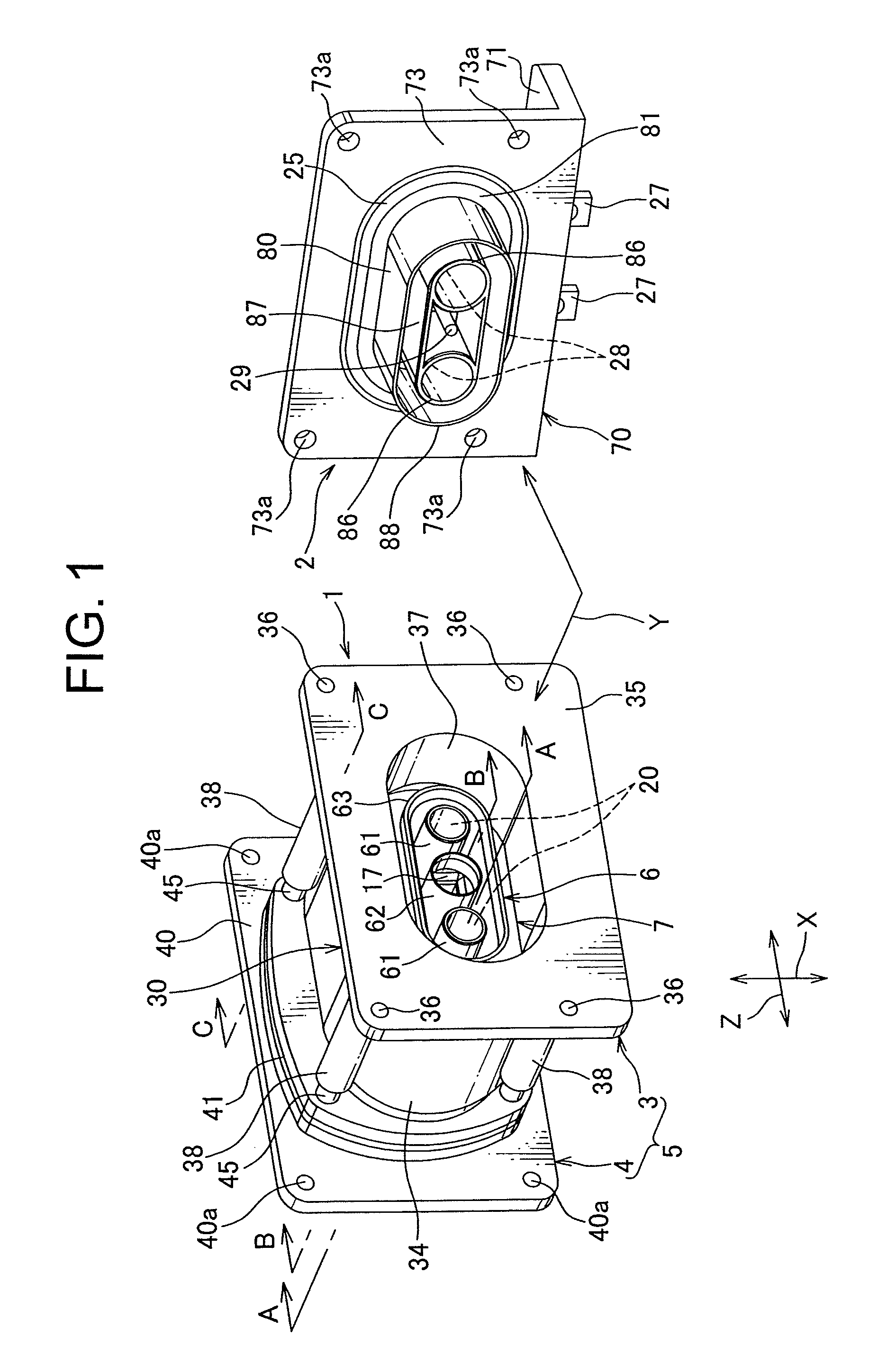
[0048]Hereafter, a connector according to a first embodiment in the invention is described with reference to FIGS. 1 to 11.

[0049]A connector 1 according to the invention is mounted in an inverter case attached to an automobile and is a receiving connector that is connected to a mating connector 2 attached to a motor case. In case that the inverter is mounted in the motor, the connector 1, i.e., is a receiving connector that is directly connected to the mating connector provided integrally with the motor.

[0050]An arrow Y shows a direction of an engagement between the mating connector and the connector 1, and a allow X shows a width direction of orthogonal oriented direction to the engaging direction and a allow Z shows a length direction of orthogonal oriented direction to the engaging direction.

[0051]The mating connector 2 mentioned above, as shown in FIGS. 1 and 6, includes a aluminum shield case 70 attached to the motor case, a synthetic-resin connector 80 mounted in the shield ca...


PUM


Abstract

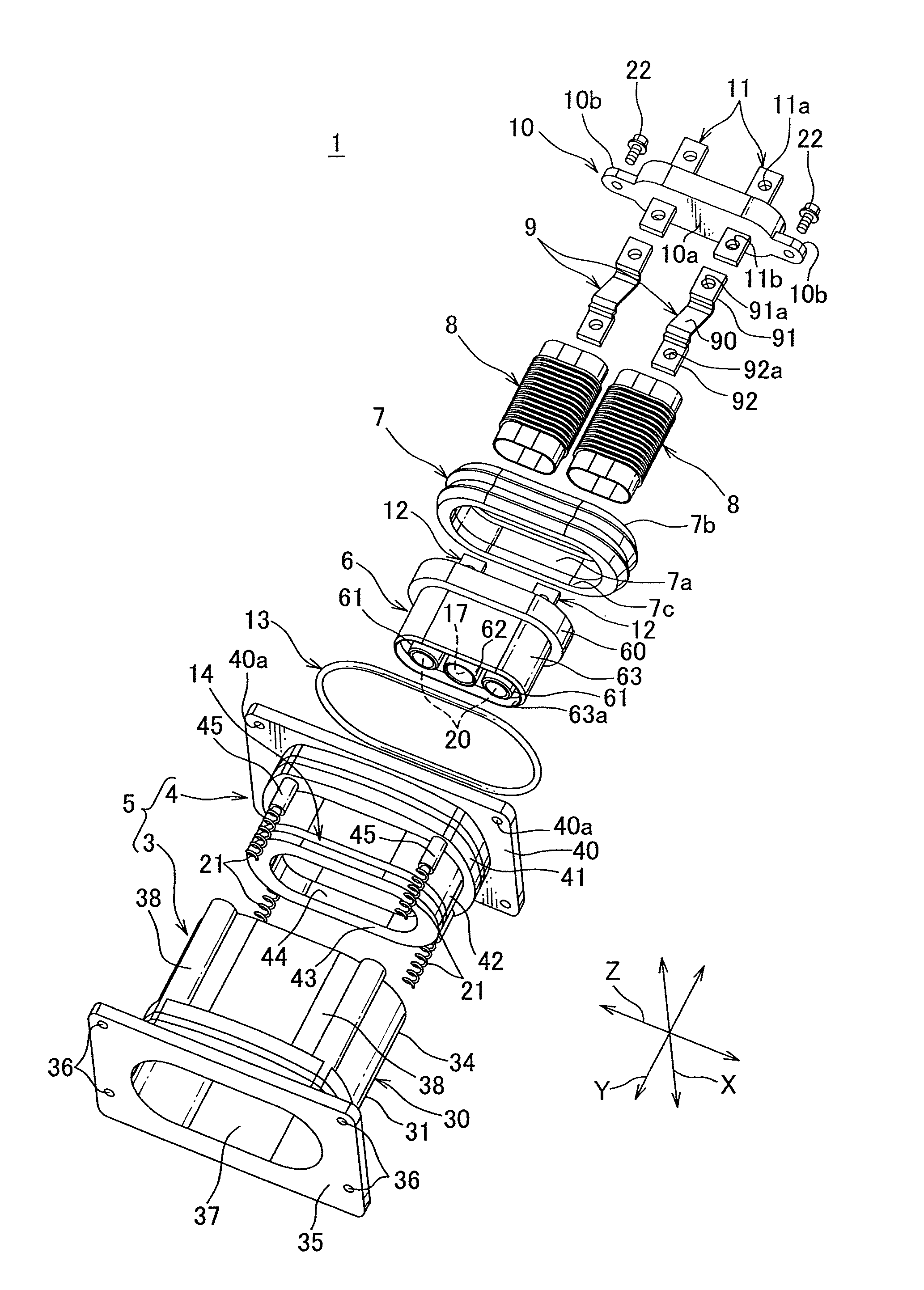
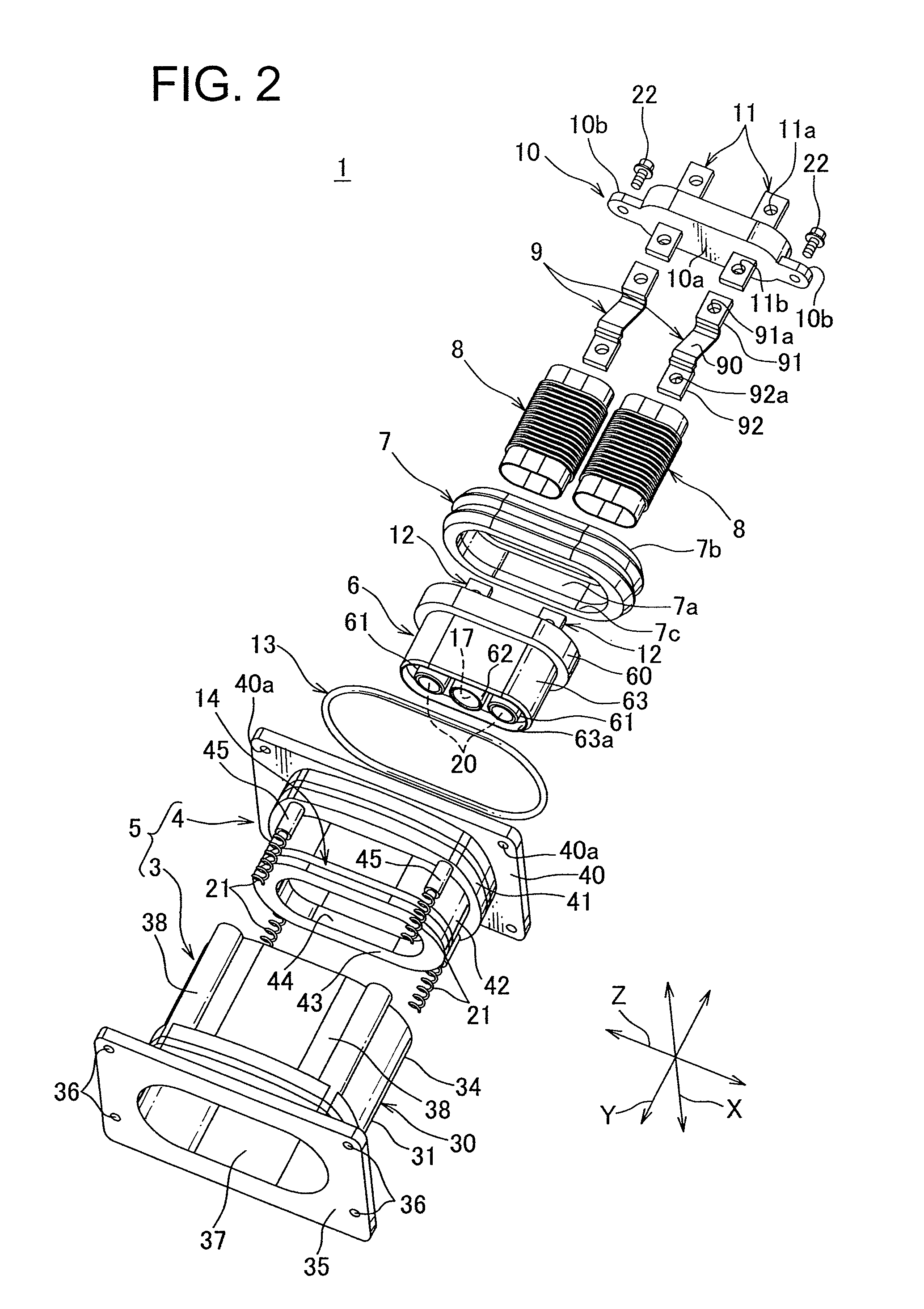
There is provided a connector 1 connected to a mating connector, fixed in a case of a motor, comprising: an outer housing 5 attached to the case; a first inner housing 6 accommodating a first terminal 20 engaging to the mating connector, being accommodated in the outer housing 5 movably in the engaging direction Y of the first terminal 20 and in the intersectional direction of the engaging direction Y; a first inner connector 6 engaging to the mating connector; a second inner housing 10 accommodating a second terminal 11 electrically connected to a electric circuit in the case and being fixed in the outer housing 5 and a braided wire 90, and further including a connection portion 9 connecting the first terminal 20 and the second terminal 11 and a packing 7 attached to the first inner housing.

Description

CROSS REFERENCE TO RELATED APPLICATIONS[0001]This application is a National Stage of International Application No. PCT / JP2010 / 057236, filed on Apr. 23, 2010, which claims priority from Japanese Patent Application No. 2009-180451, filed Aug. 3, 2009, the contents of all of which are incorporated herein by reference in their entirety.BACKGROUND OF THE INVENTION[0002]1. Field of the Invention[0003]The present invention relates to a connector used for connecting electric devices to each other.[0004]2. Description of the Related Art[0005]Various electric devices are mounted in an automobile. A conventional wire harness has been used for connecting these electric devices to each other. The wire harness comprises a plurality of electric wire and a plurality of connectors attached to the ends of the electric wire. Each connection of the wire harness to a receiving connector fixed to a case of each electric device allows the electric devices to connect to each other. Note that the receiving ...

Claims


Application Information

Patent Timeline
Patent Type & Authority Patents(United States)
IPC IPC(8): H01R13/64
CPCH01R4/70H01R13/502H01R13/6315H01R2201/26H01R13/5219
Inventor TASHIRO, HARUNORI
Owner YAZAKI CORP
Learn More