
Hooking member for in-mold molding

a technology of in-mold molding and fastening members, which is applied in the direction of snap fasteners, press-button fasteners, thin material processing, etc., can solve the problems of difficult to fit the fastening member into the recess, difficult to bend the hook member three-dimensionally, and difficult to bend the hook member roundly. , to achieve the effect of convenient bending, smooth bending and high quality appearan

Active Publication Date: 2013-03-19
KURARAY FASTENING CO LTD
View PDF14 Cites 14 Cited by
  • Summary
  • Abstract
  • Description
  • Claims
  • Application Information

AI Technical Summary

Benefits of technology

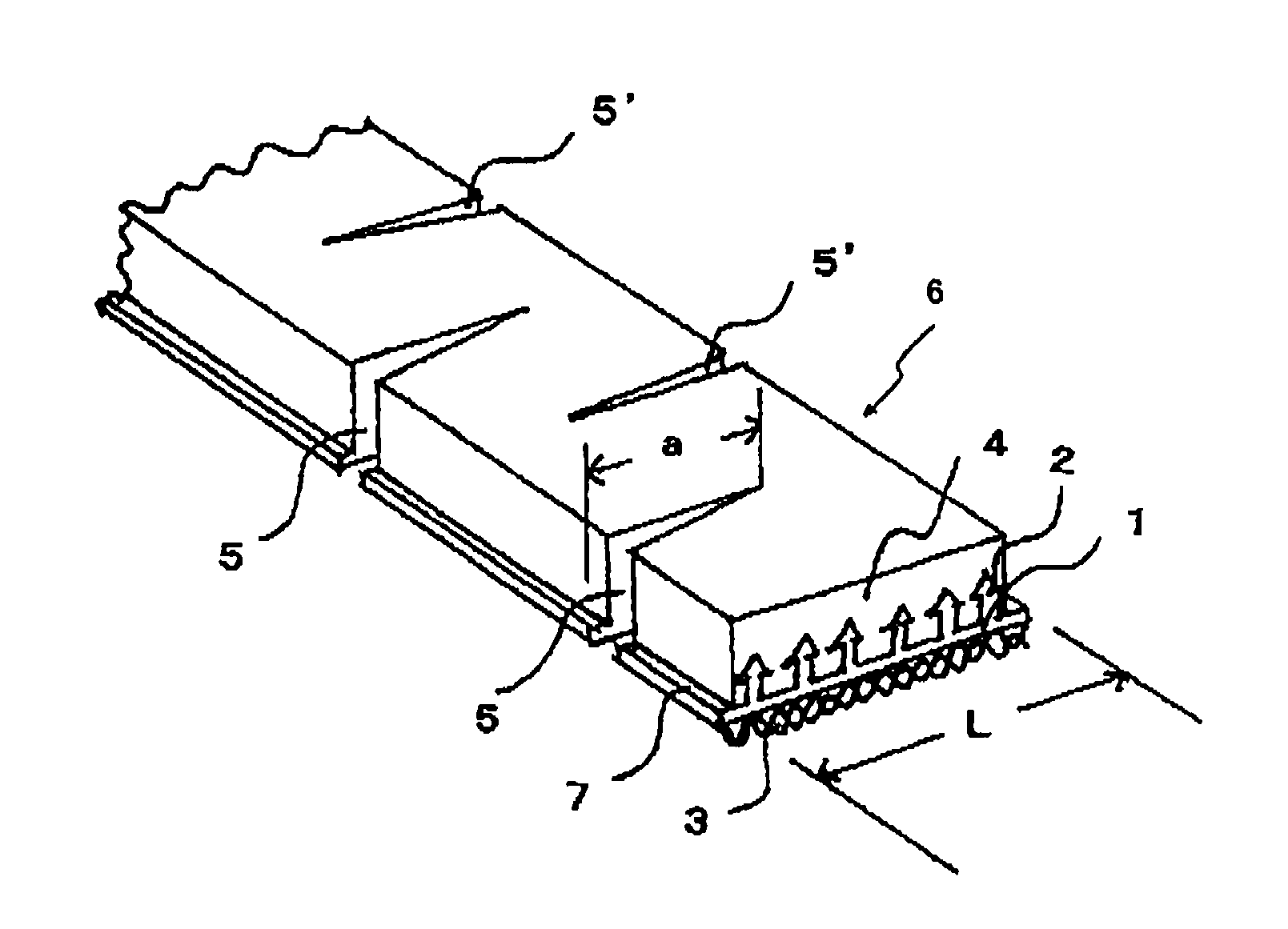
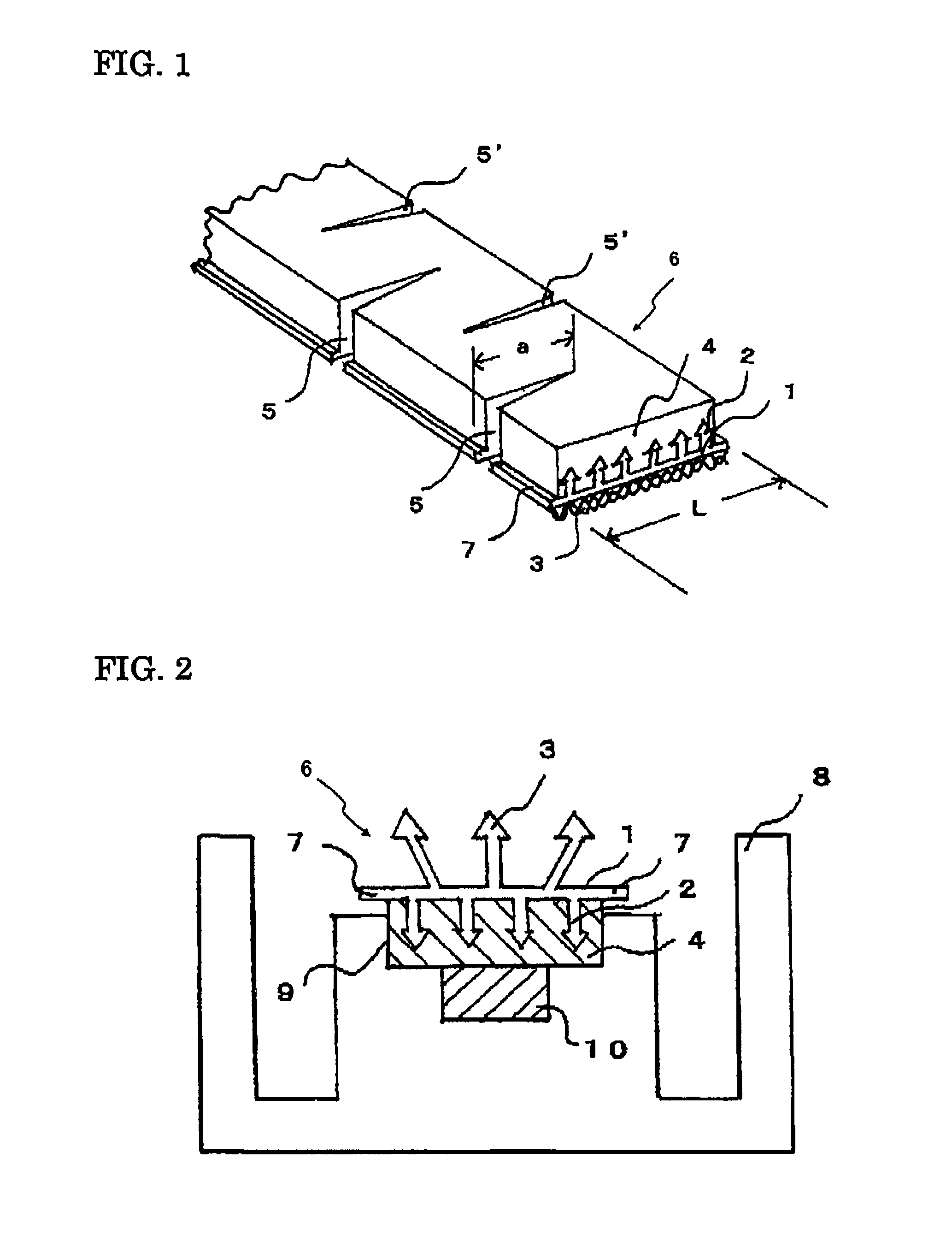
[0017]According to the present invention, a mold-in fastening member which follows a two- or three-dimensionally complicated shape of molded article is provided. The mold-in fastening member can be fixed to a desired position on the surface of a molded article of foamed resin having a complicated curved surface, such as those for seats of high-class motor cars. Since the engaging elements on the surface of the fastening member are exposed without being surrounded by a foamed resin, the engaging elements join with the cooperating engaging elements on the back side of a seat cover (upholstery material) to make the seat cover fixed to the molded article. Thus, the seat cover covers the surface of the resin molded article to give an automotive seat with a high-quality appearance.
[0019]As mentioned above, in the present invention the combination of the elastomer layer covering the engaging elements and the slits or notches extending the widthwise direction of the fastening member allows the deformation in conformity with the two- or three-dimensionally complicated curved surface.

Problems solved by technology

Recently, the structure and design of seat come to be complicated and widely range, and therefore, the molded article of foamed resin for seats is needed to change its shape from a flat plate shape to a two-dimensional shape and further to a three-dimensionally curved shape.
However, in the technique of incorporating the known hard hook member into the molded article of foamed resin, it is very difficult to bend the hook member three-dimensionally (bend the hook member roundly) and to produce a molded article while preventing the surface having engaging elements from being surrounded by the resin.
For example, a known hard hook member is hardly bent sideways in nearly parallel to the hook surface, i.e., hardly bent in plane because of its poor elasticity.
Therefore, it is quite difficult to fit the fastening member into the recess in a mold by bending it roundly so as to follow the three-dimensionally curved recess.
As described above, it is very difficult to bend a known fastening member roundly so as to conform to the three-dimensionally curved surface.
As a result, the hook surface of the fastening member is covered by the foamed molding resin and the hook elements lose the engaging function because the foamed molding resin covering the fastening member is difficult to remove.
However, the problem of the surface of engaging elements to be covered by the foamed molding resin is not solved so greatly and the proposed method is not so effective if the in-plane deformation is large and the width of substrate is large.

Method used


Image

  • Hooking member for in-mold molding
  • Hooking member for in-mold molding
  • Hooking member for in-mold molding

Examples


example 1

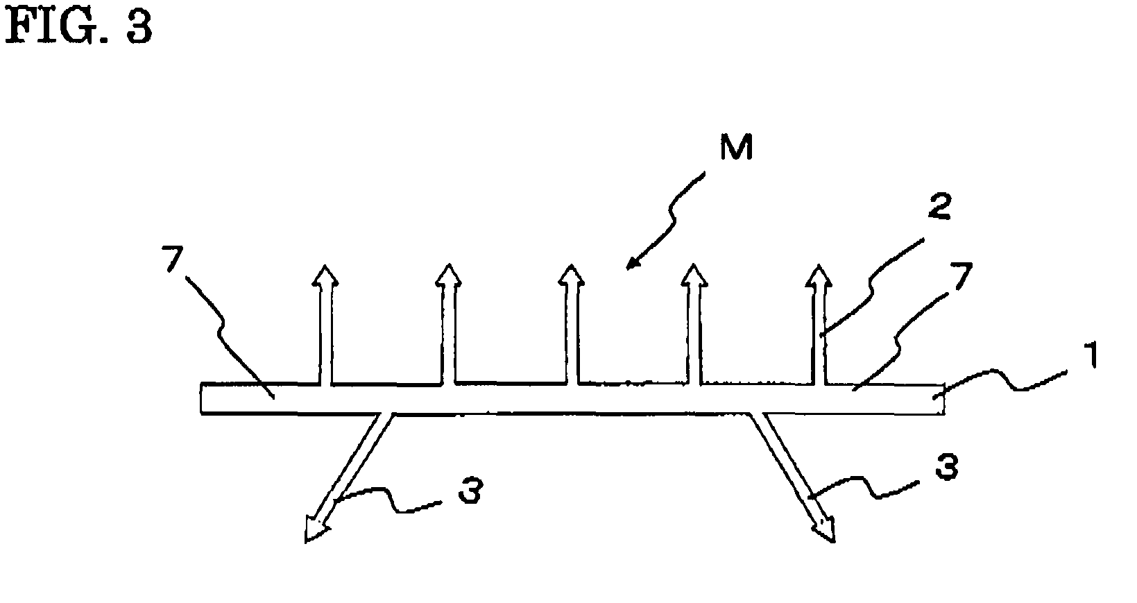
[0065]A polypropylene resin composition was prepared by adding 10% by weight of an olefin-based elastomer (V0131 manufactured by Sumitomo Chemical Company, Limited) to a polypropylene resin containing 0.5% by weight of titanium oxide. The polypropylene resin composition was extruded from an extrusion nozzle having a slit into a strip of shaped article which has a cross section as shown in FIG. 3, in which the engaging elements 2 was formed on the upper surface of the substrate 1 and the anchoring elements 3 was formed on the back surface of the substrate. The continuous ridge of engaging elements 2 was slit up to its foot at intervals of 0.3 mm and then the strip of shaped article was stretched by 3 times in the lengthwise direction, to produce a main structure M of the mold-in fastening member.

[0066]The obtained main structure M of the mold-in fastening member had the substrate of 12 mm wide and 0.5 mm thick. The substrate had on its upper surface the arrowhead hook engaging elemen...

example 2

[0074]A cushion having the fastening member was produced in the same manner as in Example 1 except for changing the wedge-shaped notches to the simple slits. The simple slits were formed by simply cutting with a cutting blade having a width of 0.2 mm without removing a portion of the substrate, elastomer layer and anchoring elements in wedge form. The obtained fastening member was slightly poor in the lateral bending. As compared with any of comparative examples, however, the fastening member bent in good conformity with the three-dimensional shape and fitted to the mold recess properly. In the cushion produced by filling the mold with the foamable liquid resin, the elastomer layer was substantially free of the foamed urethane and the elastomer layer was easily peeled off from the engaging elements from its one end. The widthwise end portions were completely embedded in the foamed polyurethane. With such end portions and the anchoring elements, the fastening member was not peeled of...


PUM

PropertyMeasurementUnit
widthaaaaaaaaaa
widthaaaaaaaaaa
widthaaaaaaaaaa

Abstract

A mold-in fastening member which is composed of a strip of substrate, engaging elements formed on one surface of the substrate, and an elastomer layer completely surrounding the engaging elements, the substrate having slits or notches which extend from a widthwise central portion of the substrate to a widthwise end portion of the substrate. The mold-in fastening member bends in conformity with a two- or three-dimensionally complicated shape of a molded article. The mold-in fastening member prevents the surface having the engaging elements from being covered with a foamable liquid molding resin during a mold-in process, thereby preventing the engaging elements from losing the engaging function.

Description

TECHNICAL FIELD[0001]The present invention relates to a mold-in fastening member which is attached to the surface of a molded article of foamed resin for use as a cushion for automotive seats and office chairs at the tune of its molding, and further relates to a production method of a molded article of foamed resin having the fastening member attached on its surface.[0002]The molded article of foamed resin having the fastening member is made into a seat by covering its surface with an upholstery material such as cloth and then joining the engaging elements of the fastening member with the cooperating engaging elements on the back surface of the upholstery material thereby fixing the upholstery material to the molded article of foamed resin.BACKGROUND ART[0003]The seat of automotive seats and office chairs is composed of a cushion made of a foamed urethane, etc. and a seat cover (upholstery material) covering the surface of cushion.[0004]In the production of automotive seats, a so-ca...

Claims


Application Information

Patent Timeline
Patent Type & Authority Patents(United States)
IPC IPC(8): A44B18/00B32B3/06
CPCA44B18/0076Y10T428/24314Y10T428/24017Y10T428/24008Y10T24/2792Y10T24/2783
Inventor ITOH, HIROSHIONO, SATORU
Owner KURARAY FASTENING CO LTD
Learn More