
Floating ice sheet based renewable thermal energy harvesting system

a renewable thermal energy and floating ice sheet technology, applied in domestic cooling devices, lighting and heating devices, domestic applications, etc., can solve the problems of potential global sea-level rise, negative environmental consequences, and massive emissions of pollutants, and achieve the effects of reducing sea ice area, reducing greenhouse gas emissions, and large-scale operation

Inactive Publication Date: 2013-03-12
RIC ENTERPRISES
View PDF4 Cites 12 Cited by
  • Summary
  • Abstract
  • Description
  • Claims
  • Application Information

AI Technical Summary

Benefits of technology

[0003]The present invention is intended to provide devices, methods and systems for harvesting renewable energy which can be cost-effective, large-scale, not dependant on any fossil fuel sources, and free of any greenhouse gas emissions; to provide real and substantial benefits to humanity and to our global environment. Regional benefits for polar regions include mitigation of sea ice area reduction and thinning caused by global warming, reduced extinction threat to polar bears, and provision of clean renewable energy for polar communities.

Problems solved by technology

The continued use of fossil fuels to meet current and emerging energy needs also has very negative environmental consequences, including massive emissions of pollutants and exacerbation of global warming.
Other frightful consequences range from decimation of polar bear populations, to a potential global sea-level rise that could even submerge whole nations such as Kiribati and the Maldives.

Method used


Image

  • Floating ice sheet based renewable thermal energy harvesting system
  • Floating ice sheet based renewable thermal energy harvesting system
  • Floating ice sheet based renewable thermal energy harvesting system

Examples


Embodiment Construction

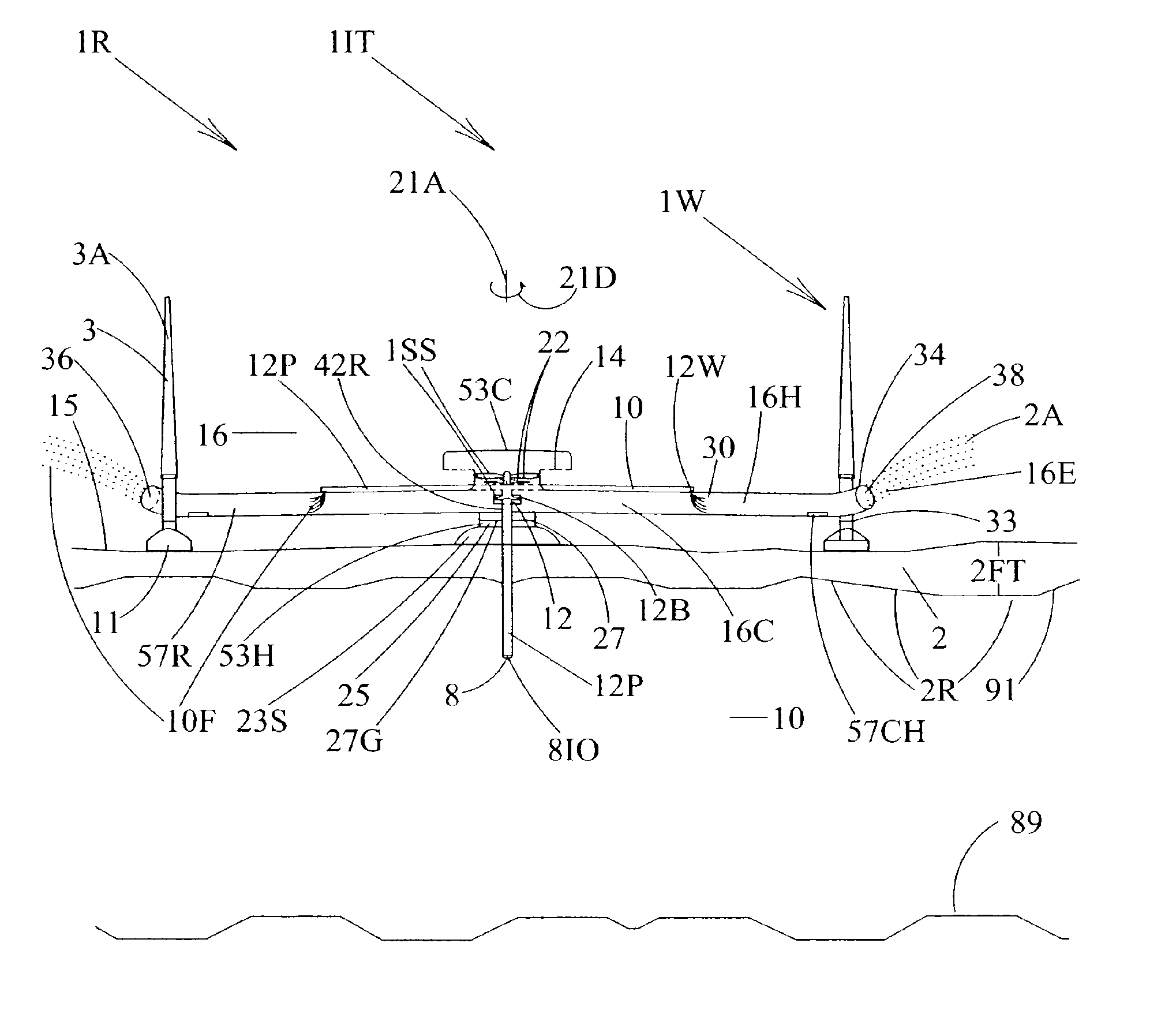
[0023]FIG. 1A shows a partial side view of a preferred embodiment of a renewable thermal energy harvesting system 1R. The renewable thermal energy harvesting system 1R is sited on a floating ice sheet 2, such as sea ice in high latitude regions such as the Arctic or Antarctic, or ice shelves or lake ice or other floating ice. The floating ice sheet 2 floats on a layer of liquid water 10 that rests on a ground surface 89. The top of the floating ice sheet 2 is defined by a frozen surface 15, and the bottom of the floating ice sheet 2 is defined by an ice / water interface comprising the undersurface 91 of the floating ice sheet. The illustrated renewable thermal energy harvesting system 1R is supported at least in part by support means 23S adjacent the upper surface of the floating ice sheet 2. The illustrated renewable thermal energy harvesting system 1R is intended to harvest two types of renewable energy: the first being renewable thermal energy using a thermodynamic cycle engine th...


PUM


Abstract

The invention provides a floating ice sheet based renewable thermal energy harvesting system, that can harvest energy from naturally occurring temperature differential between liquid water below a floating ice sheet that is substantially at the freezing temperature of water (0 degrees C. or slightly lower for salt water), and colder air above the floating ice sheet. For example, this is a naturally occurring phenomenon in Arctic and Antarctic region sea ice or ice shelf regions, where the air temperature above the floating ice may range from −5 degrees C. down to winter extreme cold temperatures of around −50 degrees C. In addition to the inventive application of thermodynamic cycle engines to harvest renewable energy from this naturally occurring temperature differential, variant embodiments also combine wind energy and / or solar energy subsystems to provide synergistic further benefits and greater quantities of renewable energy harvestable from devices of this class.

Description

BACKGROUND OF THE INVENTION[0001]As the World's human population grows and as the economic prosperity of that population grows, the energy demand of that population also grows. With limited availability of oil reserves, there is a growing need for the conception, development and deployment of cost-effective and large-scale renewable energy alternatives. The continued use of fossil fuels to meet current and emerging energy needs also has very negative environmental consequences, including massive emissions of pollutants and exacerbation of global warming. One of the most ominous threats of all comprises global warming induced Arctic ice depletion. Polar scientists generally agree that global warming induced Arctic ice depletion will occur on a large scale in the coming decades, and will include both Arctic sea ice depletion and Kalaallit Nunaat (Greenland) and Antarctic ice cap depletion. Ice thinning, ice area reduction, and rising waters are among the many consequences that could r...

Claims


Application Information

Patent Timeline
Patent Type & Authority Patents(United States)
IPC IPC(8): F25C3/04
CPCF03G7/04
Inventor SANKRITHI, MITHRA M. K. V.SANKRITHI, SIVA U. M.
Owner RIC ENTERPRISES
Learn More