
WLAN communication device

a communication device and communication technology, applied in wireless communication, data switching networks, wireless communication, etc., can solve the problems of process consuming resources of master terminals, awkward sharing of wireless broadband connection among several users (client terminals), and affecting the service life of wireless broadband modems, so as to achieve the effect of reducing battery consumption

Active Publication Date: 2013-03-05
HUAWEI TECH CO LTD
View PDF54 Cites 152 Cited by
  • Summary
  • Abstract
  • Description
  • Claims
  • Application Information

AI Technical Summary

Benefits of technology

The patent text describes a way to save battery power on a communication device by using a processor to set up timer functions. One timer activates the WLAN circuitry periodically to search for new signals, while another timer checks if the WLAN circuitry is still active. If no activity is detected for a while, the WLAN circuitry is deactivated to save battery power. This technique helps to minimize battery consumption and improve the device's overall performance.

Problems solved by technology

Prior art wireless broadband modems exhibit certain problems.
For instance, sharing a single wireless broadband connection among several users (client terminals) is awkward at best.
This process consumes resources of the master terminal and the client terminals cannot operate without the master.
Another problem of prior art wireless broadband modems is the fact that most of them are “wireless” only towards the mobile network and the connection to the client terminal takes place via a USB cable.
Yet another problem is that the bandwidth provided by a mobile station and access network may be insufficient, particularly when several client terminals share a single wireless broadband connection.

Method used


Image

  • WLAN communication device
  • WLAN communication device
  • WLAN communication device

Examples


Embodiment Construction

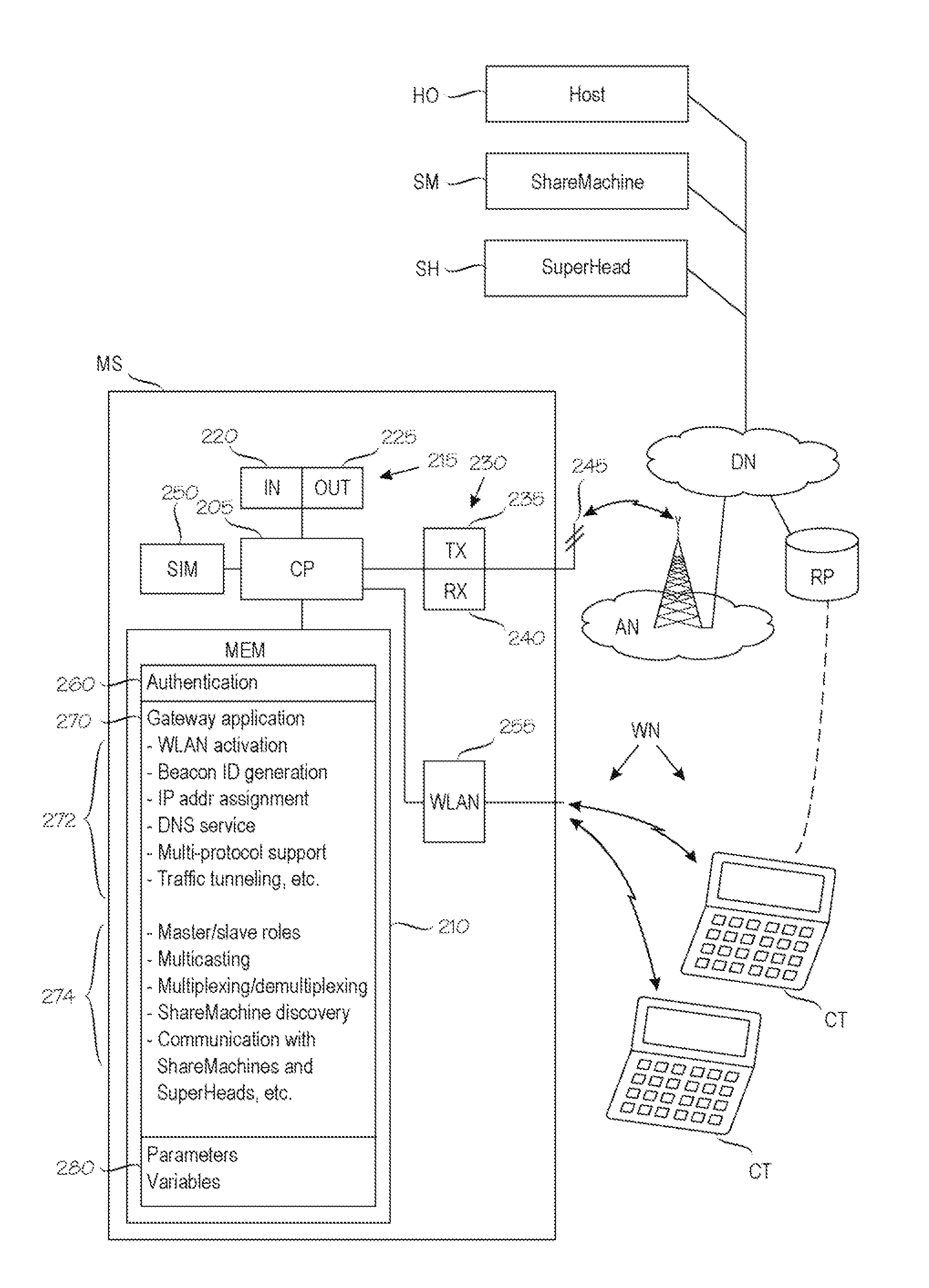
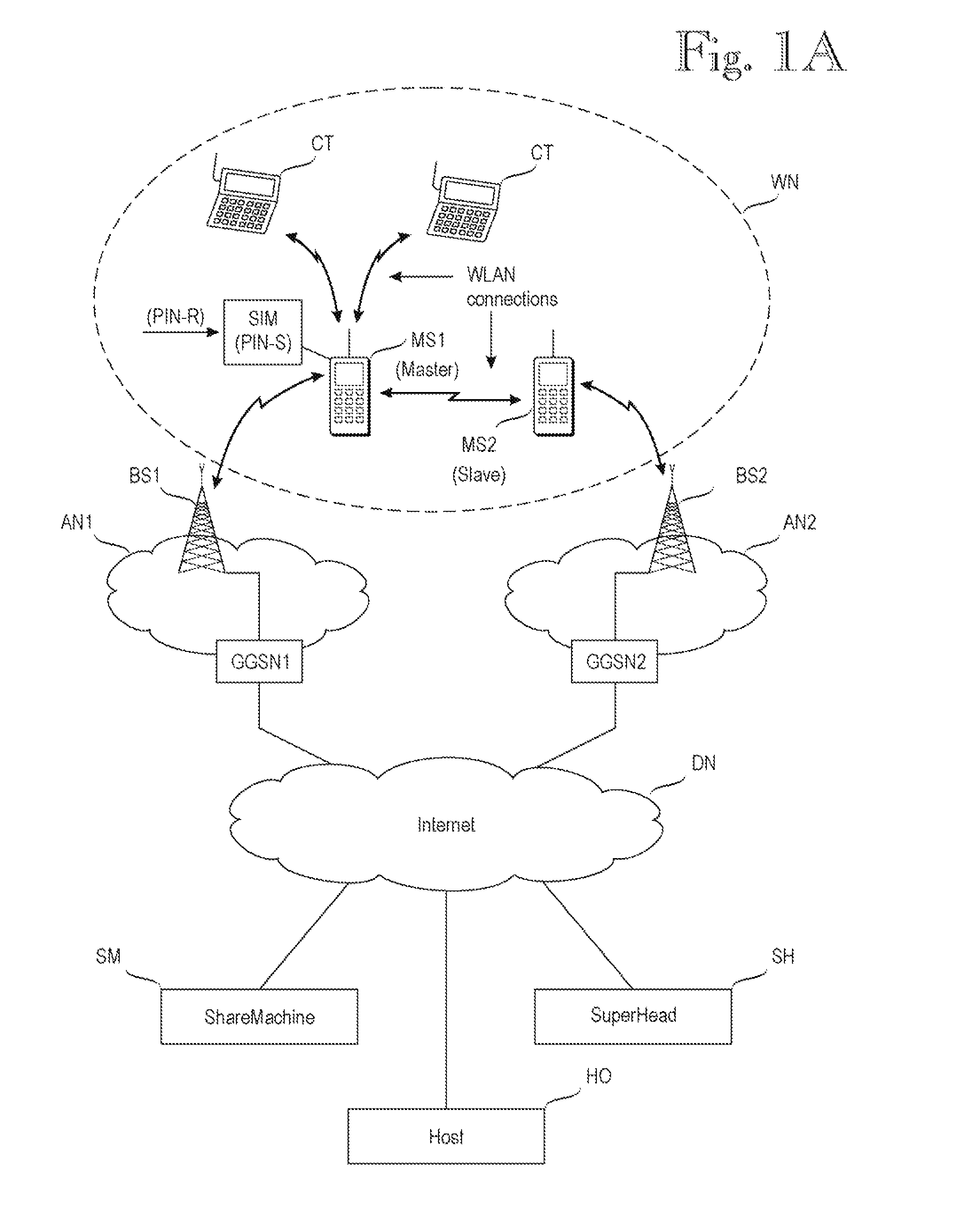
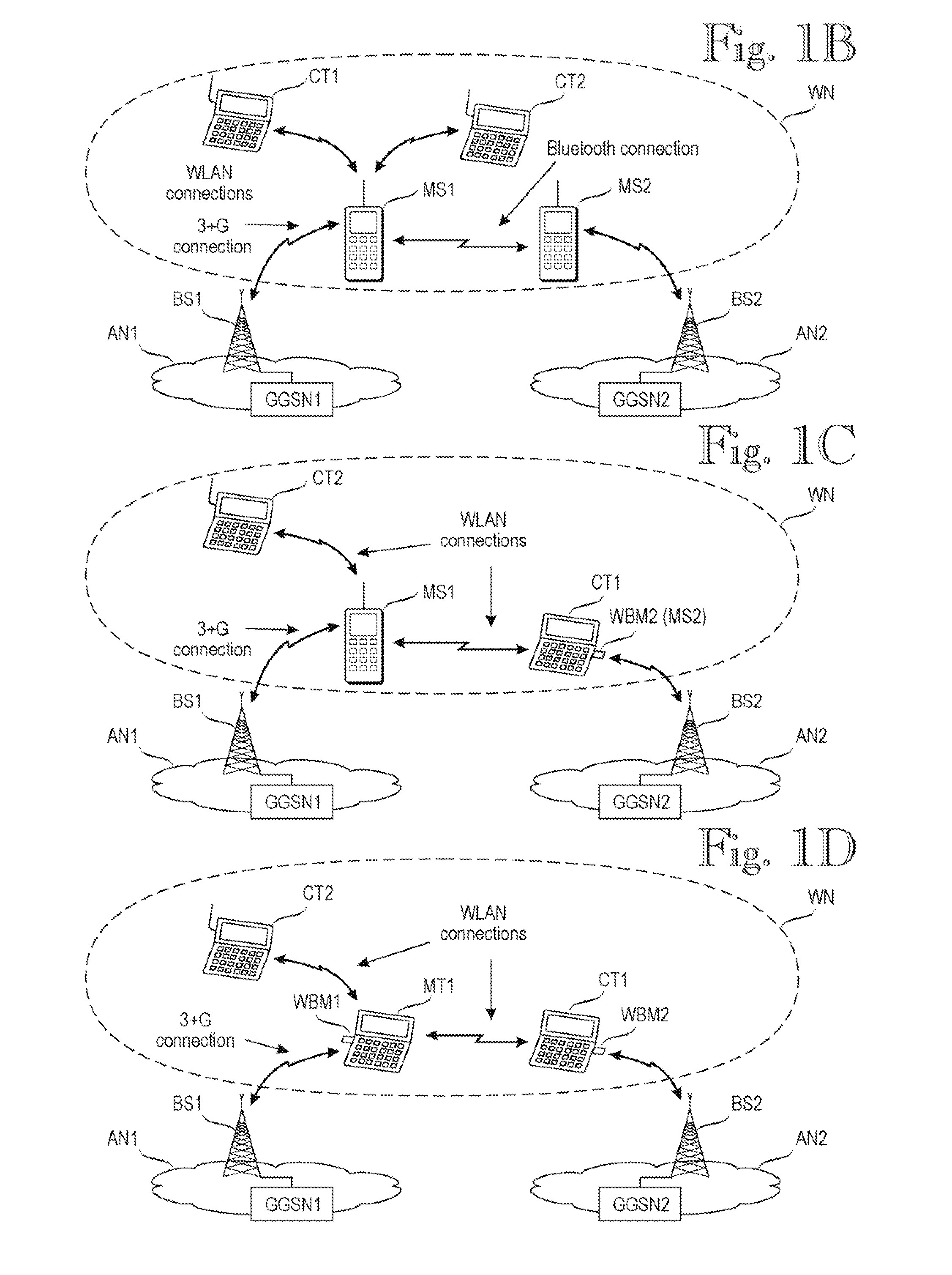
[0032]FIG. 1A is a schematic view of a general network architecture in which the invention can be used. In the illustrative but non-restrictive use case shown in FIG. 1A, a first mobile station MS1 represents the inventive communication device; the radio communication section of the first mobile station MS1 represents the first wireless broadband communication device; a second mobile station MS2 represents the second wireless broadband communication device; while any one of WLAN client terminals CT represents the claimed data processing device capable of acting as a WLAN client terminal.

[0033]Reference documents 1 and 2 (commonly owned patent applications, unpublished at the filing date of the present application, which is why some key sections of their contents are repeated here) discloses a technique in which mobile station MS establishes an ad-hoc WLAN network WN and acts as a gateway for providing a single communication path between one or more a client terminals CT and an Inter...


PUM


Abstract

A technique for combining transmission bandwidths of several communication devices, such as mobile stations is disclosed. A master mobile station establishes a WLAN access point communicating with WLAN client terminals. One or more slave mobile stations may detect a predefined network identifier and join the WLAN network. The master assigns IP addresses for the client terminals and slave mobile stations. The master also resolves DNS queries in cooperation with external DNS servers. Traffic, including internet packets, between the client terminals and various internet hosts is tunneled over multiple simultaneous transmission paths between the master and a multiplexing / demultiplexing computer). The inventive bandwidth combination technique is transparent to the client terminals and the internet hosts.

Description

PARENT CASE INFORMATION[0001]The present application is a national-phase application of and claims priority from PCT application PCT / FI2009 / 050771, filed 28 Sep. 2009.FIELD OF THE INVENTION[0002]The invention relates to methods, apparatuses and software products for providing a wireless broadband internet connection via a mobile communication network. In the context of the present invention, a broadband connection means a connection capable of transmitting traffic, in good network conditions, faster than a V.90 modem can, or faster than 64 kilobits per second.BACKGROUND OF THE INVENTION[0003]Wireless broadband modems can be used to couple personal computers or client terminals to the internet in places where wired internet connections or local-area networks are not available. Prior art wireless broadband modems exhibit certain problems. For instance, sharing a single wireless broadband connection among several users (client terminals) is awkward at best. Normally this requires setti...

Claims


Application Information

Patent Timeline
Patent Type & Authority Patents(United States)
IPC IPC(8): H04W92/04H04W12/06H04W4/00H04L12/28
CPCH04L29/12216H04L61/2007H04W12/06H04W76/022H04W84/20H04W28/08H04L29/12066H04L29/12226H04L29/12367H04L61/1511H04L61/2514H04W8/26H04W88/04H04L61/2015H04W76/12H04L61/5007H04W28/088H04L61/4511H04L61/5014
Inventor MAKI, LASSEOJALA, TOM
Owner HUAWEI TECH CO LTD
Learn More