Tool condition monitoring system

a condition monitoring and tool technology, applied in the field of tools, can solve the problems of difficult correct control and/or regulation of the tool operating condition, uncritical operating parameters of another blade of the same cutting tool, and high risk

Inactive Publication Date: 2013-02-19
KISTLER HLDG AG
View PDF15 Cites 1 Cited by
  • Summary
  • Abstract
  • Description
  • Claims
  • Application Information

AI Technical Summary

Benefits of technology

[0012]Thus, the object of the present invention is to provide a tool in which the detection of an operating parameter, such as for example a force, a pressure or a temperature, which has an impact on a tool element, for example a blade of the tool, can be determined in a more reliable and more simple manner.
[0027]The single blade force measurement at the blade head with the blade front cutting head according to the present invention described above, exhibits numerous advantages with respect to the disadvantages of RCDs specified in the beginning. In particular, the sensors may clearly shed light on all components of the cutting force, i.e. on the horizontal force portions and / or the normal force portions of the cutting force at the individual tool blade. Each blade is clearly assigned to an individual force signal, so that the information is not provided in form of a complex total signal. Thus, the non-negligible effort for the identification of individual signal portions from the total signal can be avoided, or the reliable evaluation of individual specific signal portions of a tool element may be reliably realized for the first time at all, particularly since the poor signal resolution of the tools known from the prior art includes a high risk of misinterpretation in particular for inexperienced users. The reduction of the number of possible signal forms is a substantial factor, which enables the fundamental evaluability of complex signals for the first time in a reliable manner, in particular in the case, when inevitable signal dynamics of the tool spindle system occur in addition to the static force signals.

Problems solved by technology

On a drill head of a tunnel drilling machine or a drilling machine for drilling for natural resources, like petroleum or gas, or on drilling machines for geological investigations, on a tool formed as a drill head, usually several material cutting elements, like blades, elements for crashing or grinding and similar elements are typically provided, each of which may simultaneously be exposed to different values of the same operating parameter, which makes the correct control and / or regulation of the tool in operating condition very difficult.
Thus, for example with a cutting tool, which has several blades, one blade may be very heavily loaded, for example with a high operating pressure, a high cutting force or a high temperature, while another blade of the same cutting tool is subject to the predetermined uncritical operating parameters.
The result is that the tools known from the prior art are not optimally controllable and / or adjustable, which may lead to poor working results, and can e.g. result in a lack of quality of a manufactured product, or in the worst case in the failure or the damage of the tool and machine elements attached thereto.
Despite various application options of RCDs in the context of process monitoring and analysis, the systems exhibit certain disadvantages due to their conceptual design.
With RCDs, a single blade monitoring is only possible by removing all but one blade.
The evaluation and interpretation of such signals are extremely demanding due to the large number and variations of signal forms.
Upon simultaneous superposition of oscillations of the tool spindle system the separation of the force components from the total signal and the assignment to individual blades prove to be problematic.
In individual cases, these difficulties even determine whether the signal can be evaluated at all.
Furthermore, the constant component within the total signal is subject to a signal drift at a longer cutting duration.
This means that despite a force is constantly applied, the drift causes a signal decrease and thus the measuring error constantly increases over time.
Since the stator has to be mounted at the spindle head side, a reconstruction is required, which possibly limits the accessibility.
Upon stimulations in the proximity of the resonant frequency oscillation forms may occur, which do no longer allow any signal interpretation.
Furthermore the pulse-type stimulation only insignificantly differs by the blade engagement impact from the engagement-related signal forms whereby in particular the automated processing proves to be very difficult.
Consequently, the measured signal no longer perfectly reflects the process at increased stimulation frequencies, but increasingly represents the oscillation behaviour of the mass located upstream.
However, these applications have the important disadvantage that the mass located upstream of the sensor is clearly larger than with RCDs, and that the measurement takes place still farther remote from the cutting site.
The mass-related deficiencies of the sensor application mentioned with respect to cutting force dynamometers arise to an increasing degree, and further disturbing factors influence the signal input, so that the measuring result illustrates the process of interest with a correspondingly increased uncertainty.
Further, the mass located upstream of the sensor is very high, so that the system exhibits low natural frequencies, whereby no high-speed processes can be examined.

Method used


Image

  • Tool condition monitoring system
  • Tool condition monitoring system

Examples


Embodiment Construction

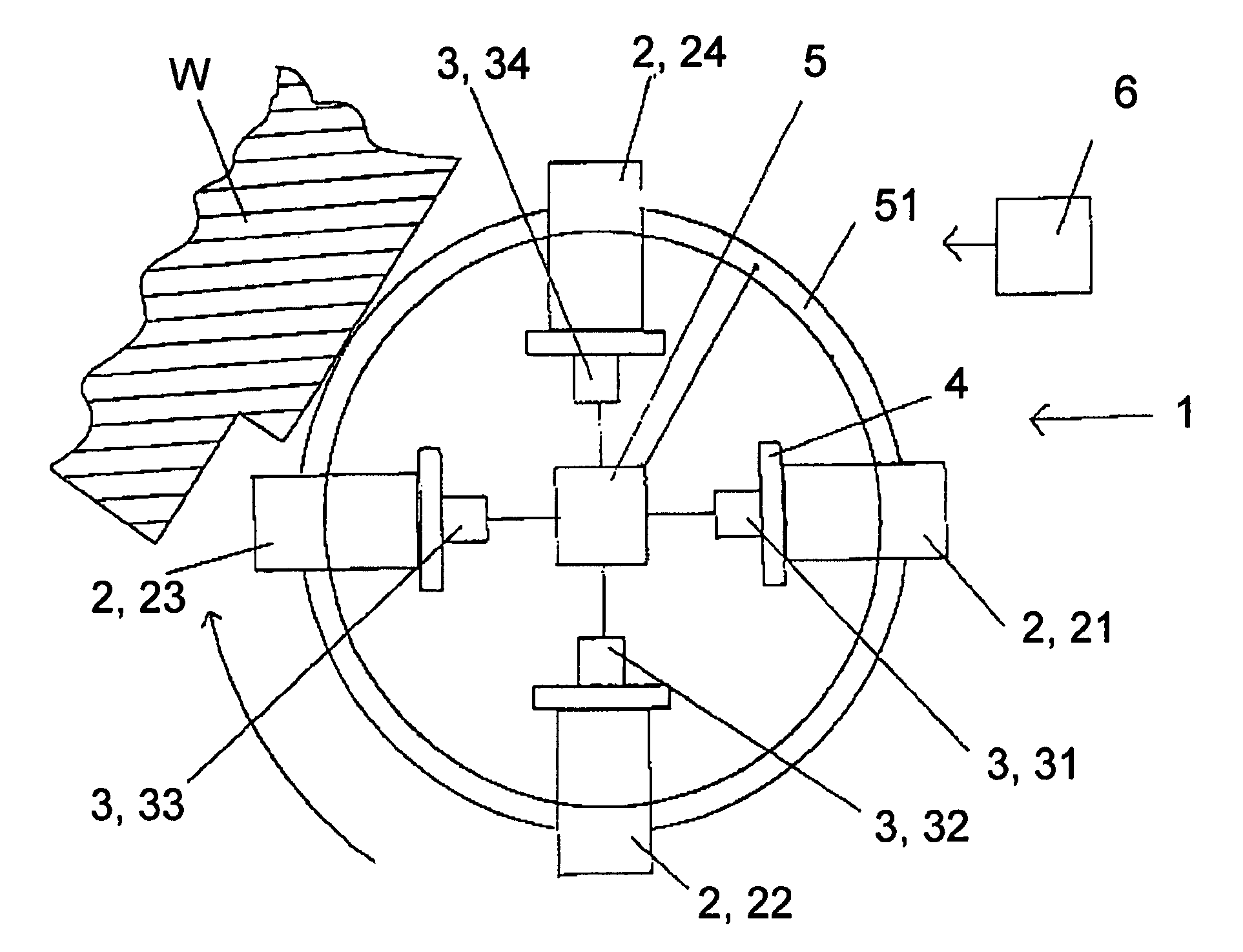
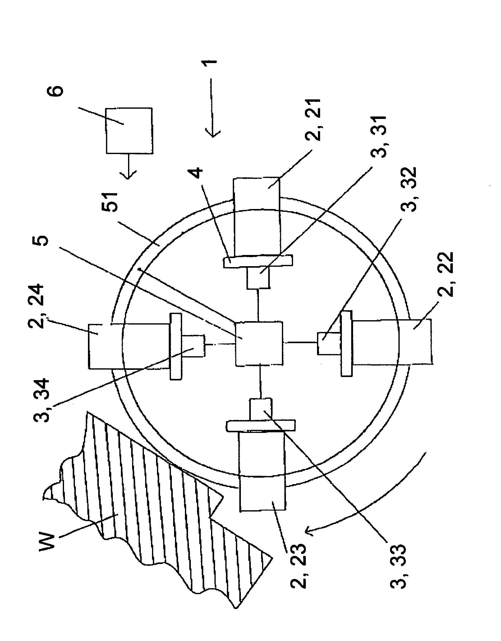
[0030]FIG. 1 shows a tool according to the invention in a schematic illustration in form of a blade front cutting head with single blade force measurement, which tool in the following is indicated entirely by the reference numeral 1.

[0031]The blade front cutting head 1 rotating in operation is schematically illustrated in FIG. 1 in operating condition, wherein the blade front cutting head 1 processes a surface of a work piece W, by cutting material of a given thickness at the surface of work piece W. In the particular embodiment of FIG. 1 four tool elements 2, 21, 22, 23, 24 are provided at the blade front cutting head 1 in the form of four geometrically defined cutting plates 2, 21, 22, 23, 24, which process the work piece W at its surface in a cutting manner. Each of the four cutting plates 2, 21, 22, 23, 24 is coupled via a coupling element 4 formed as an intermediate disk 4 to an assigned measuring device 3, 31, 32, 33, 34 each, by which measuring device 3, 31, 32, 33, 34 an ope...


PUM

PropertyMeasurementUnit
resonant frequencyaaaaaaaaaa
weightaaaaaaaaaa
pressureaaaaaaaaaa

Abstract

The invention relates to a tool having a tool element which rotates in operation with at least one geometrically defined blade, in particular a material cutting tool element. The tool element is subject to an operating parameter in the operating condition. A measuring device is provided for determination and conversion of the operation parameter into a measured signal. A first measuring device cooperates with a first tool element in the operating condition such that essentially only a first operating parameter for the first tool element may be recorded by the first measuring device.

Description

CROSS-REFERENCE TO RELATED APPLICATIONS[0001]This application claims priority to Swiss Application No. 1430 / 05 filed Aug. 31, 2005 and International Application Serial No. PCT / CH2006 / 000470 filed Aug. 30, 2006.TECHNICAL FIELD[0002]The present invention relates to a tool comprising a tool element, in particular a material cutting tool element according to the preamble of the independent claim 1. In particular, the invention relates to a blade front cutting head with single blade force measurement.PRIOR ART[0003]From the prior art, a plurality of material cutting tools is known, by means of which various materials are processed. For example, said tools are cutting tools, such as drills, cutters, planers or tools of all kinds, e.g. for the use in a turning lathe. In addition, tools for crashing or crushing certain materials, such as rock, metal, glass, plastics, composite materials or other materials inter alia are intended to be a tool in the sense of the present application. Said too...

Claims


Application Information

Patent Timeline
Patent Type & Authority Patents(United States)
IPC IPC(8): B23B29/24
CPCB23C5/00B23Q17/09G05B19/4065B23C2260/76Y10T408/165G05B2219/37355G05B2219/50347Y10T408/38Y10T83/849
Inventor SCHAFFNER, GEORGESSTIRNIMANN, JOSEFKIRCHHEIM, ANDREASVESELOVAC, DRAZENSCHMITZ, RENE
Owner KISTLER HLDG AG
Why Eureka
Try Eureka