
Conveyor mover

a technology of conveyer and moving body, which is applied in the direction of transportation and packaging, transportation of items, packaging, etc., can solve the problem of not intended summary

Inactive Publication Date: 2013-02-05
JESSE LYNN
View PDF16 Cites 9 Cited by
  • Summary
  • Abstract
  • Description
  • Claims
  • Application Information

AI Technical Summary

Benefits of technology

[0011]The extension of the jack causes the drive wheel or drive wheels on the drive axle of the mover to be lowered into a ground engaging position and whereby further extension of the jack applies downward pressure to the drive wheel or drive wheels on the drive axle to increase traction thereof with the retraction of the jack causing the drive wheel or drive wheels on the drive axle to be raised relative to the conveyor framework axle to a transport position. In the preferred embodiment, the drive wheel or drive wheels are lowered by the jack until the support wheel of the conveyor framework is lifted from the ground thereby applying sufficient weight to the drive wheel or drive wheels to provide sufficient traction.
[0017]A further object of the invention is to provide a conveyor mover of the type described which ensures that the drive wheel or drive wheels thereon will have sufficient traction to move the conveyor from one location to another.
[0019]A further object of the invention is to provide a conveyor mover which is easily attached to a conventional conveyor whether it be of the grain auger type or the grain conveyor belt type.

Problems solved by technology

Moreover, this Summary is not intended for use as an aid in determining the scope of the claimed subject matter.

Method used


Image

  • Conveyor mover
  • Conveyor mover
  • Conveyor mover

Examples


Embodiment Construction

[0028]Embodiments are described more fully below with reference to the accompanying figures, which form a part hereof and show, by way of illustration, specific exemplary embodiments. These embodiments are disclosed in sufficient detail to enable those skilled in the art to practice the invention. However, embodiments may be implemented in many different forms and should not be construed as being limited to the embodiments set forth herein. The following detailed description is, therefore, not to be taken in a limiting sense in that the scope of the present invention is defined only by the appended claims.

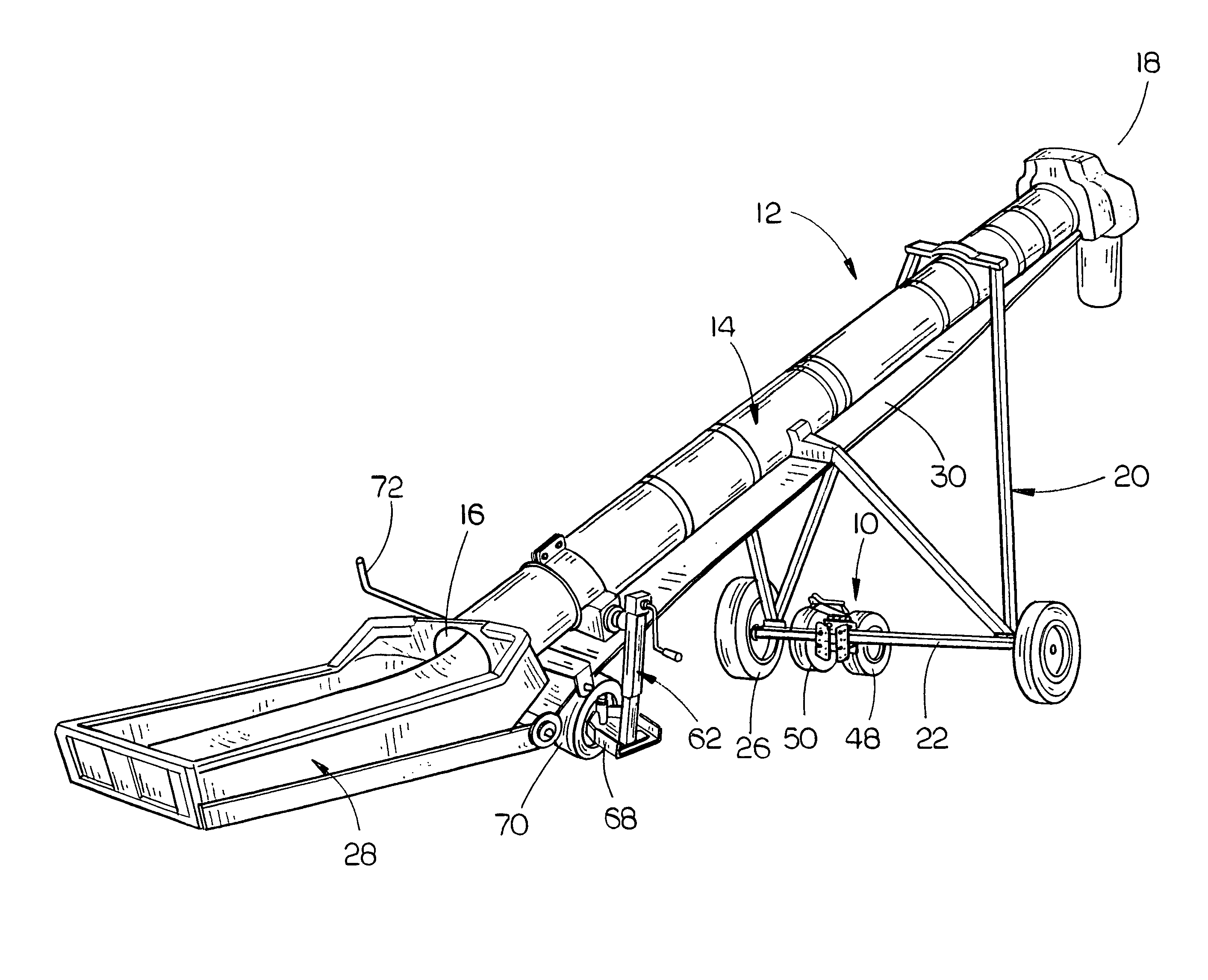
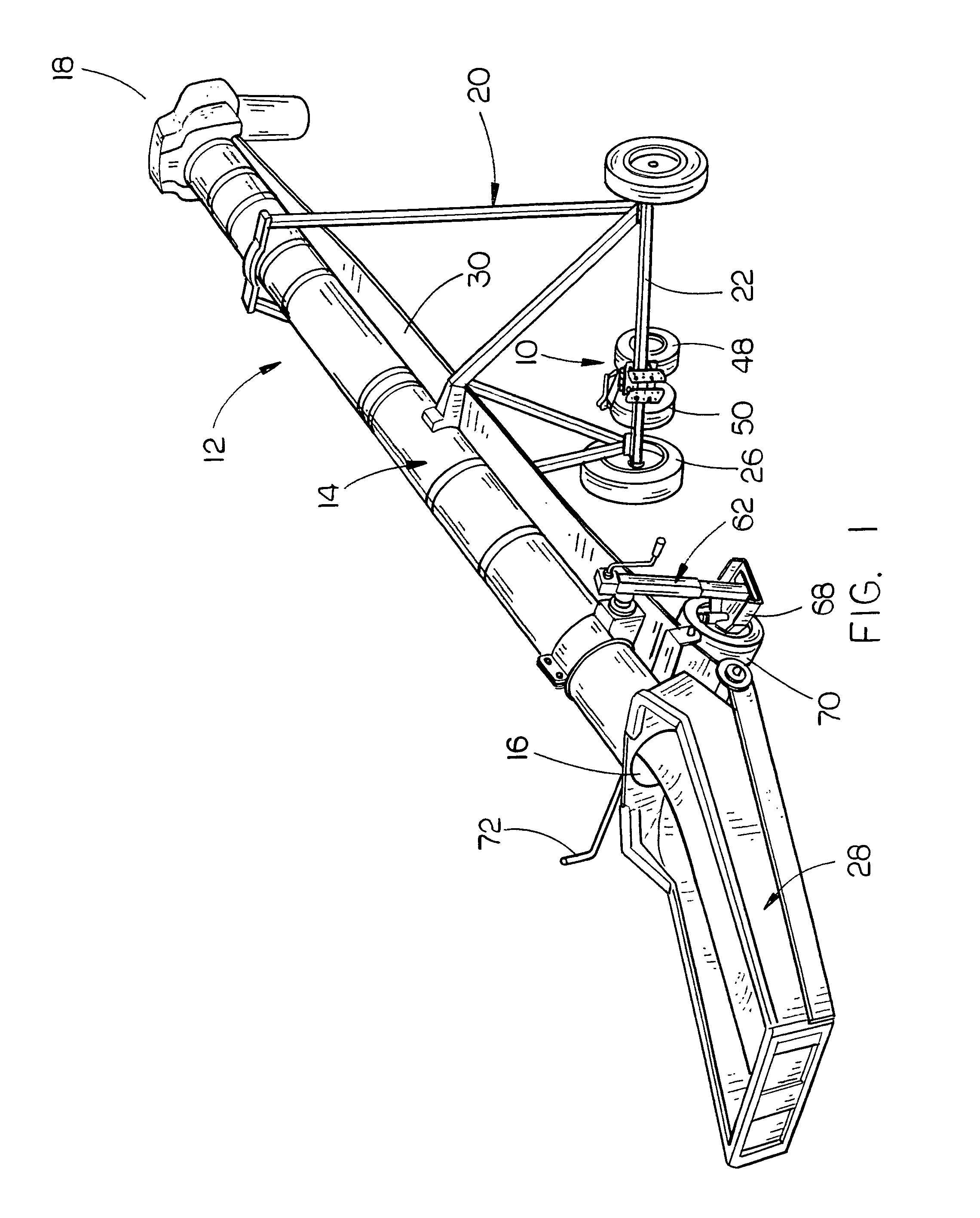
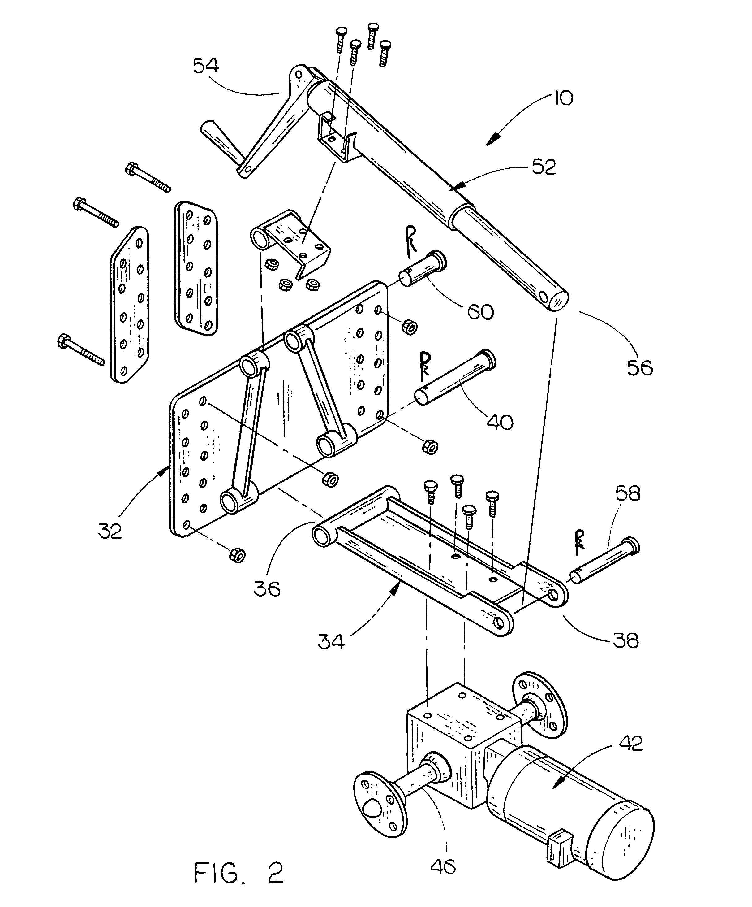
[0029]The numeral 10 refers generally to the conveyor mover of this invention which is designed to move a conveyor 12 either forwardly or rearwardly. The conveyor 12 may be a belt conveyor such as illustrated in the drawings or an auger conveyor such as disclosed in the co-pending application. In either case, the conveyor 12 may be used to convey particulate material such as grain ...


PUM


Abstract

A conveyor mover which may be used to move an auger conveyor or a belt conveyor from one location to another such as between grain bins. The mover is secured to the framework axle of the conveyor and is movable between a lower ground engaging position to an upper transport position. The mover includes at least one drive wheel which may be driven in either a forward direction or a rearward position. In one embodiment, a steer wheel assembly is secured to the conveyor tube adjacent the lower end thereof.

Description

CROSS-REFERENCE TO RELATED APPLICATION[0001]This application is a continuation-in-part of Applicant's earlier application and claims the benefit of application Ser. No. 12 / 930,537, filed on Jan. 10, 2011, now U.S. Pat. No. 8,118,151, entitled A GRAIN AUGER MOVER.BACKGROUND OF THE INVENTION[0002]1. Field of the Invention[0003]This invention relates to a conveyor mover and more particularly to a remotely controlled conveyor mover which may be attached to the axle of the conveyor with the mover being selectively movable between operative and transport positions. Even more particularly, this invention relates to a conveyor mover which may be used with an auger type conveyor or a belt type conveyor with the conveyor being adapted to convey particulate material such as grain or the like.[0004]2. Description of the Related Art[0005]Conveyors for conveying particulate material such as grain are normally of the auger type or of the conveyor belt type. In either case, the conveyor includes an...

Claims


Application Information

Patent Timeline
Patent Type & Authority Patents(United States)
IPC IPC(8): B65G21/00
CPCB65G33/14B65G41/002B65G41/008
Inventor JESSE, LYNN
Owner JESSE LYNN
Learn More