
Indexable shoe cleat with improved traction

a technology golf cleats, which is applied in the field of indexable shoe cleats with improved traction, can solve the problems of limited japana publication, inability to selectively position japana cleats, and inability to index or orient japana cleats in specific or selected different positions. to achieve the effect of minimizing damage to turf surfaces and improving traction

Inactive Publication Date: 2005-06-14
SOFTSPIKES
View PDF163 Cites 85 Cited by
  • Summary
  • Abstract
  • Description
  • Claims
  • Application Information

AI Technical Summary

Benefits of technology

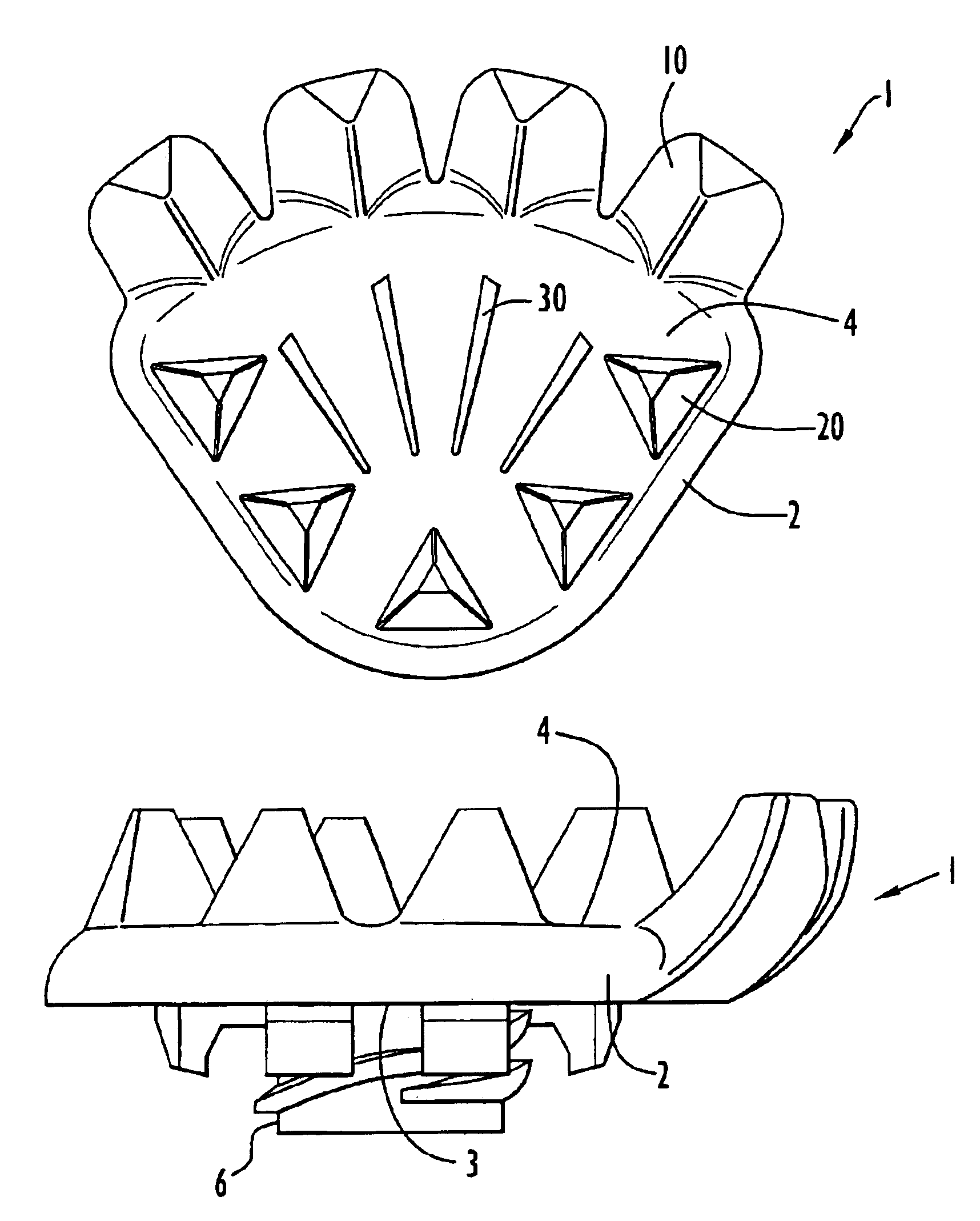
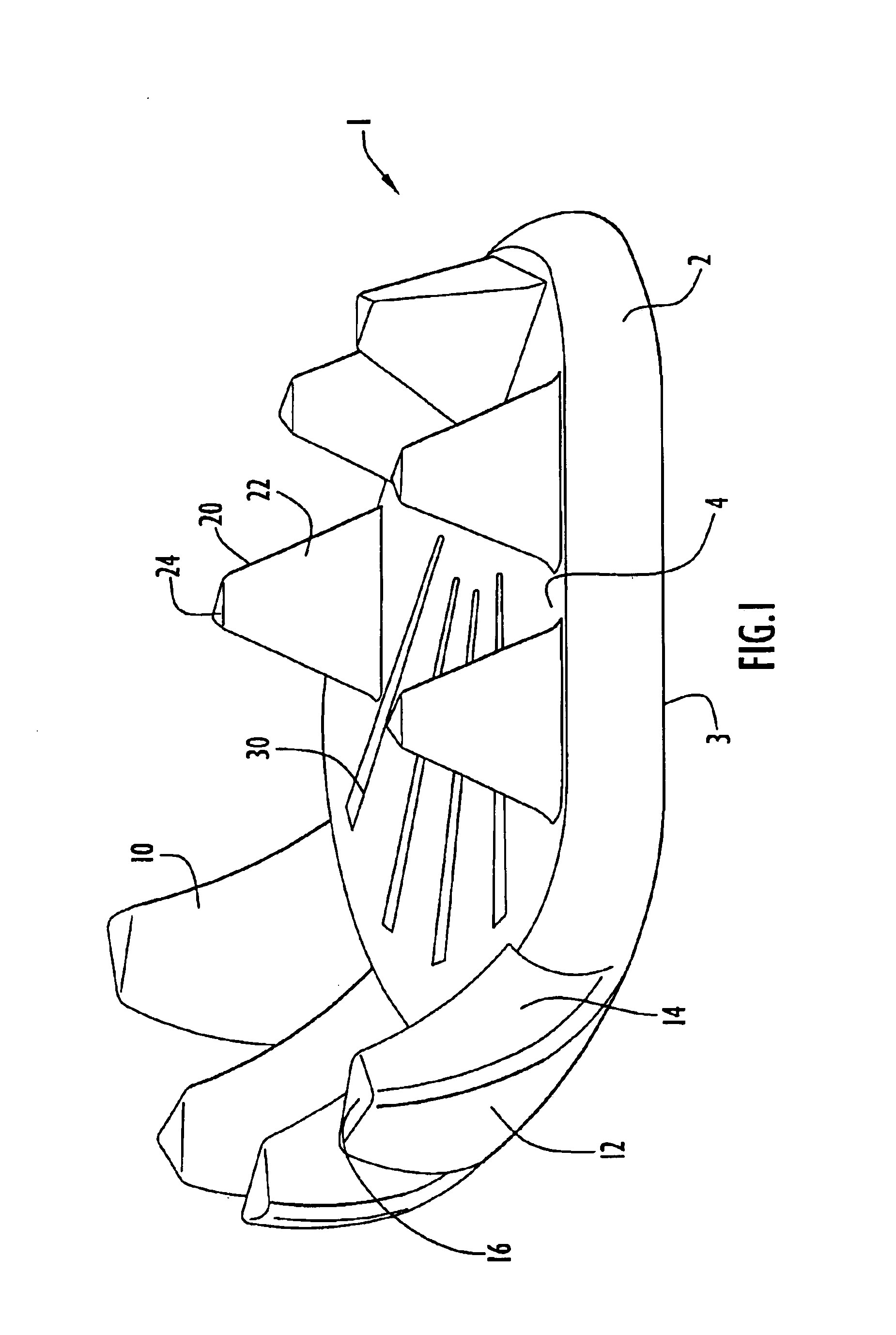
"The present invention is a shoe cleat that provides enhanced traction while minimizing damage to turf surfaces. It is designed to be securely attached to a shoe and includes a hub with a surface facing away from the shoe, at least one traction element extending from the hub, and a cleat connector securable within the shoe. The cleat connector is positioned on the hub with a radial distance between the hub perimeter and the cleat connector central axis that is different at various locations along the hub perimeter. This allows the cleat to be connected to the shoe sole in a selected configuration with respect to the shoe sole based upon a particular application and / or user preference. The invention also provides a shoe cleat that is not easily worn on hard surfaces such as concrete or asphalt yet provides a suitable level of traction for such hard surfaces. Additionally, the invention provides a shoe cleat that is indexable to facilitate a variety of orientations of the cleat with respect to the shoe."

Problems solved by technology

However, the challenge with utilizing plastic cleats is to design a cleat having suitable traction on turf surfaces while being suitably protected from wear and tear due to contact with hard surfaces such as asphalt or concrete.
The Japana publication is limited in that it only discloses symmetrically alternating long and short legs extending from the shoe sole.
Thus, the axially symmetric Japana cleat is not capable of being indexed or oriented in specific or selected different positions with respect to the shoe sole.
That is, the Japana cleat cannot be selectively positioned such that the weight bearing shorter legs and the penetrating longer legs in different alignments based upon cleat applications requiring different directions and levels of traction.

Method used


Image

  • Indexable shoe cleat with improved traction
  • Indexable shoe cleat with improved traction
  • Indexable shoe cleat with improved traction

Examples


Embodiment Construction

[0020]The present invention includes a cleat that is secured to a shoe sole to enhance traction of the shoe. Referring to FIGS. 1-3, shoe cleat 1 includes a non-circular, fan-shaped hub 2 having a top surface 3 and a bottom surface 4. It is to be understood that the terms “top surface” and “bottom surface” as used herein refer to surfaces of the shoe cleat that face toward or away, respectively, from the shoe sole. The fan-shaped hub has opposite rounded peripheral end portions of different radii of curvature. Specifically, the wider or peripherally longer arcuate end portion of the hub has a greater radius of curvature in comparison to the opposite narrower or peripherally shorter arcuate end portion. The peripheral sides of the hub diverge from respective ends of the narrow end portion and extend to respective ends of the wider end portion. However, the hub is not limited to such a configuration, and may have any suitable geometric configuration consistent with the principles desc...


PUM


Abstract

A shoe cleat with improved traction includes a hub with an exposed surface facing away from the shoe sole when the cleat is secured to the shoe, at least one traction element extending from the hub in a direction away from the exposed surface of the hub, and a cleat connector extending from a surface of the hub opposing the exposed surface and securable within a receptacle of the shoe. The cleat connector is positioned on the hub such that the radial distance defined between the hub perimeter and a central axis of the cleat connector differs at varying locations along the hub perimeter in order to facilitate different orientations of the hub with respect to the shoe sole when the cleat is secured to the shoe.

Description

BACKGROUND OF THE INVENTION[0001]1. Technical Field[0002]The present invention pertains to cleats for use with shoes worn on turf and other surfaces. In particular, the present invention pertains to a golf cleat that provides traction on various types of surfaces and for specific purposes.[0003]2. Discussion of Related Art[0004]The need for providing improved traction elements for the soles of shoes on turf surfaces is well known in the art, particularly in the field of sports such as football, baseball, soccer and golf. In many sports, particularly golf, the need for providing improved traction elements must be considered in combination with limiting the wear and tear on the playing turf that can be caused by the traction elements.[0005]In recent years, there has been a change from using penetrating metal spikes for golf shoes to removable plastic cleats that are much more turf-friendly and less harmful to clubhouse floor surfaces. However, the challenge with utilizing plastic clea...

Claims


Application Information

Patent Timeline
Patent Type & Authority Patents(United States)
IPC IPC(8): A43C15/00A43C15/16
CPCA43C15/162
Inventor MCMULLIN, FARIS W.
Owner SOFTSPIKES
Learn More