
Device and a method for controlling light emission

a technology of light emission and control device, applied in the direction of electric variable regulation, process and machine control, instruments, etc., can solve the problem of significant more difficult identification of temporary deviations in light emission for an observer of the illuminan

Inactive Publication Date: 2013-01-22
LEDON LIGHTING JENNERSDORF +1
View PDF5 Cites 11 Cited by
  • Summary
  • Abstract
  • Description
  • Claims
  • Application Information

AI Technical Summary

Benefits of technology

The patent text describes a method for controlling the light sources in an illuminant system in a way that minimizes the impact on the light emitted. This is achieved by deactivating or dimming the light sources in a specific pattern, which allows for accurate detection of the light intensity from each individual source while avoiding any perceptible lighting effects for the observer. Additionally, the length of the measuring periods can be adjusted to appropriate brightness control of the light sources. This method provides improved accuracy and control during calibration without causing any change in intensity or color.

Problems solved by technology

The fact that the light sources are now no longer always activated individually, but that the mixed light emitted by the light sources is also included at least in part, means that the temporary deviations in the light emission for an observer of the illuminant are significantly more difficult to identify.

Method used


Image

  • Device and a method for controlling light emission
  • Device and a method for controlling light emission
  • Device and a method for controlling light emission

Examples


Embodiment Construction

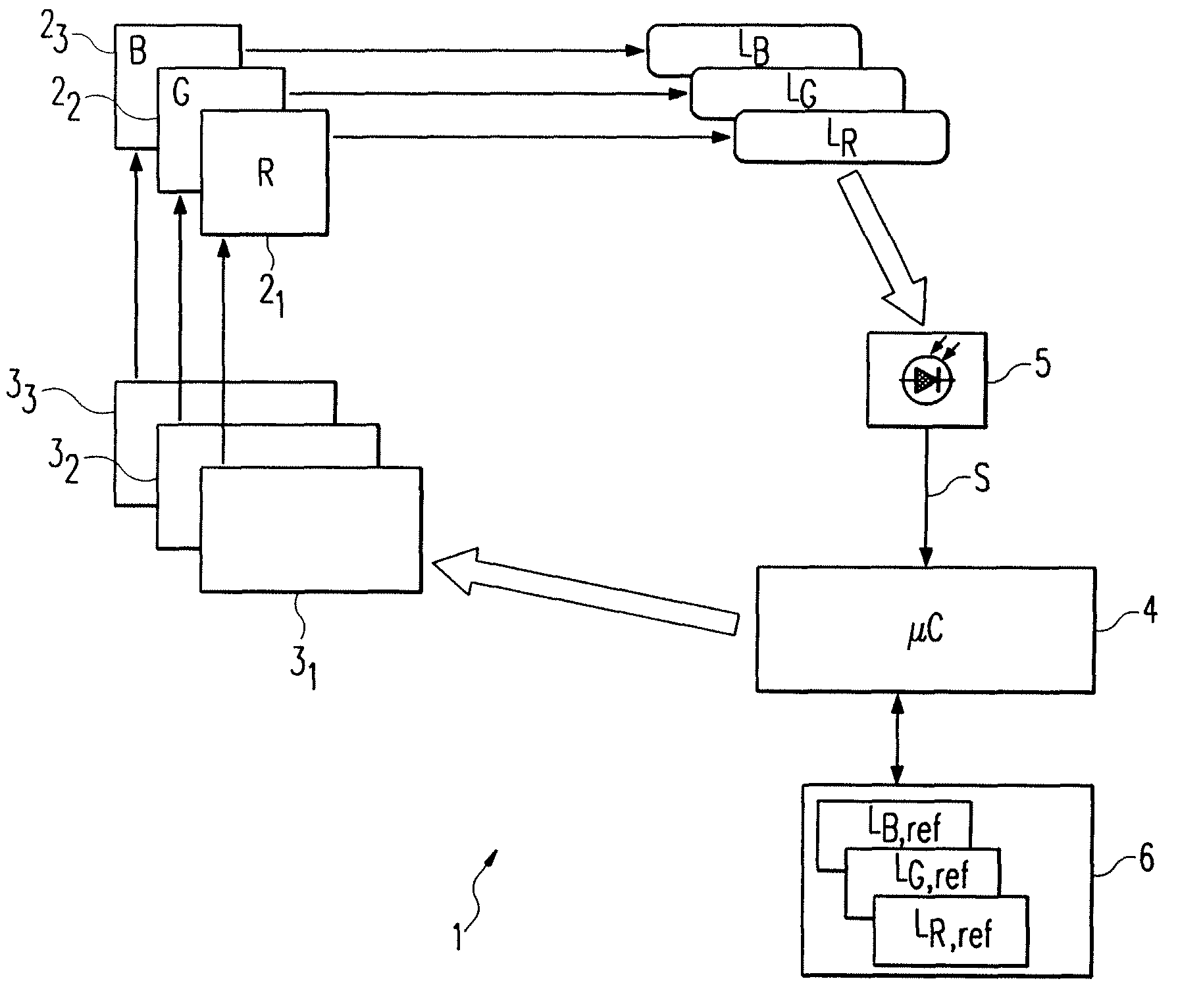
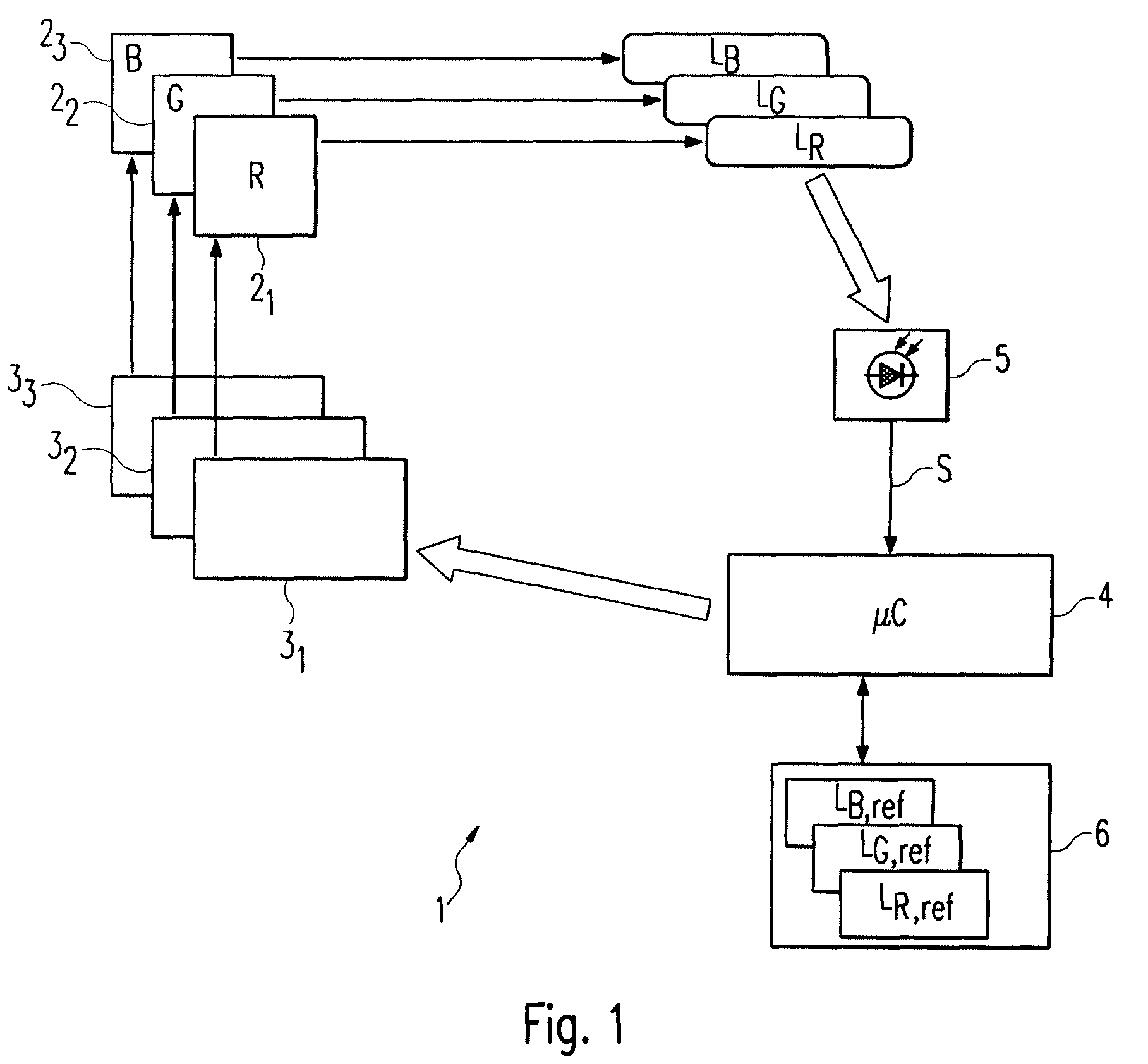
[0019]The device for light emission presented in FIG. 1 and indicated in general with the reference number 1 initially provides three light sources 21 to 23, which are designed for the emission of light in the colours red (LR), green (LG) and blue (LB). The light sources 21 to 23 can each be adjusted in their brightness independently from one another, which opens up the possibility of providing mixed light of almost any required colour shade and any desired intensity. To simplify the presentation, the optical elements required for mixing the light have not been illustrated, but these are already known from the prior art. The mutually independent control of the light sources 21 to 23 is achieved by three driver circuits 31 to 33, which supply each light source 21 to 23 allocated to them with a corresponding power. In this context, the control of the light sources 21 to 23 by the driver circuits 31 to 33 is implemented on the basis of control signals supplied to the driver circuits 31...


PUM


Abstract

The invention relates to a device and a method for controlling the light emission (i) of at least three light sources (21, 22, 23), wherein the light emitted by the light sources (21, 22, 23) is detected in a sequence of measuring periods during a calibration phase, and calculated on the basis of the information on the brightness of each individual light source (21, 22, 23) obtained during the measuring periods. In at least one of the measuring periods, the detected light comes from a plurality of the light sources (21, 22, 23).

Description

FIELD OF THE INVENTION[0001]The present invention relates to a device and method for controlling the light emission from several light sources.BACKGROUND OF THE INVENTION[0002]In recent years, LEDs or light-emitting semiconductor elements in general have been used increasingly in lighting technology because the powers attainable with light sources of this kind are now sufficiently high for relatively large lighting applications. By comparison with other types of light source, LEDs offer the advantage of a relatively greater efficiency. Furthermore, the power and therefore the brightness of an LED can be adjusted in a relatively simple manner, so that light can be generated in almost any required colour shade through a corresponding mixing of different colours.[0003]However, one problem of LED illuminants of this kind, which provide LEDs of different colours, is that these illuminants are not stable with regard to colour-location without an appropriate control or regulation on the ba...

Claims


Application Information

Patent Timeline
IPC IPC(8): H05B37/02H05B44/00
CPCH05B33/0869H05B33/0818H05B45/22H05B45/37
Inventor SEJKORA, GUENTHERHARTMANN, PAULPEREIRA, EDUARDOBARTH, ALEXANDER
Owner LEDON LIGHTING JENNERSDORF
Learn More