
Electric current supply control apparatus for glow plug, and glow plug and electric current supply apparatus connected to the glow plug

a technology of electric current supply and control apparatus, which is applied in the direction of electric control, machines/engines, instruments, etc., can solve the problems of reducing engine output or a misfire, increasing the amount of egr, and longer the time required by the engine, so as to achieve sufficient engine output, increase the circulation amount of exhaust gas, and suppress the generation of nox

Inactive Publication Date: 2013-01-08
NGK SPARK PLUG CO LTD
View PDF6 Cites 0 Cited by
  • Summary
  • Abstract
  • Description
  • Claims
  • Application Information

AI Technical Summary

Benefits of technology

The patent text describes a glow plug and electric current supply control apparatus that can increase the circulating amount of exhaust gas while maintaining engine output and reducing NOX generation. The apparatus includes an electric current supply control system that controls the amount of electric current supplied to a heat generation resistor. The resistance of the heat generation resistor is controlled to match a target resistance, which helps stabilize the temperature of the resistor during operation. The apparatus also includes a report signal that can be sent to an external device to increase the circulating amount of exhaust gas. The report signal contains information about the temperature at which the heat generation resistor is to rise, which allows the external device to increase the circulating amount of exhaust gas without causing excessive NOX generation. The apparatus can also control the temperature of the heat generation resistor to 1200°C or higher to further enhance the circulating amount of exhaust gas. Overall, the apparatus provides a simple and effective solution for increasing the circulating amount of exhaust gas and reducing NOX generation during engine operation.

Problems solved by technology

As a result, combustion of fuel becomes unstable, which may cause a reduction in engine output or a misfire.
However, the results of this test reveal that, the greater the EGR amount, the longer the time required by the engine to increase its speed from about 700 rpm to about 3000 rpm.
Further, although the EGR amount desirably is increased so as to further reduce NOX, the increased EGR amount makes combustion unstable.

Method used

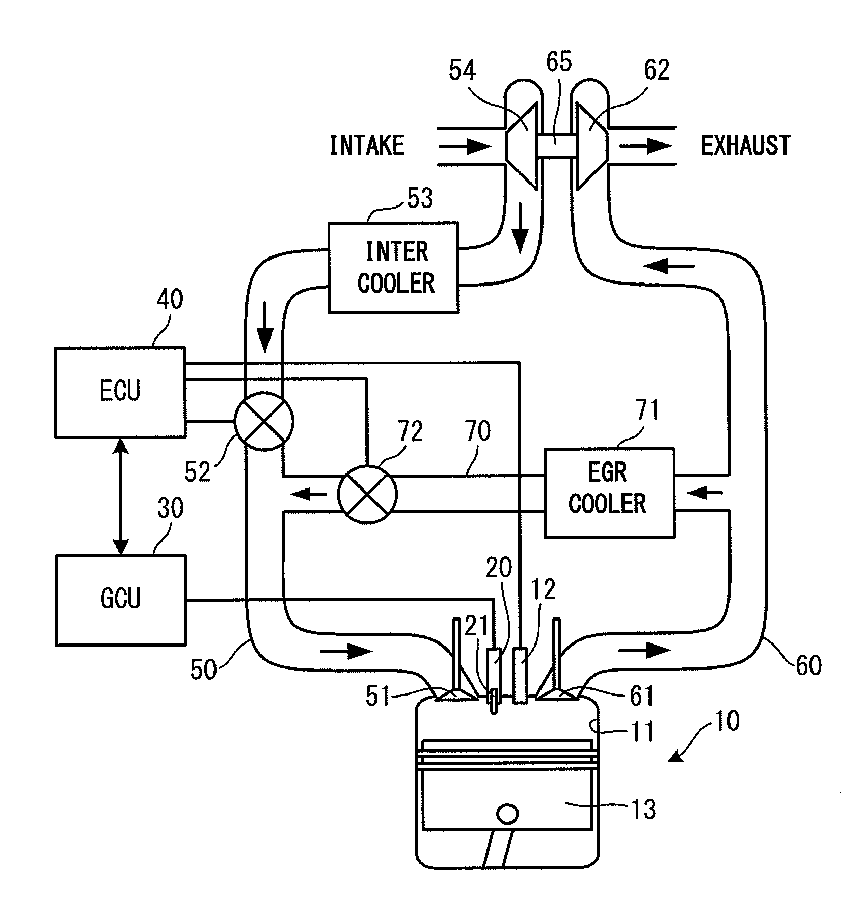
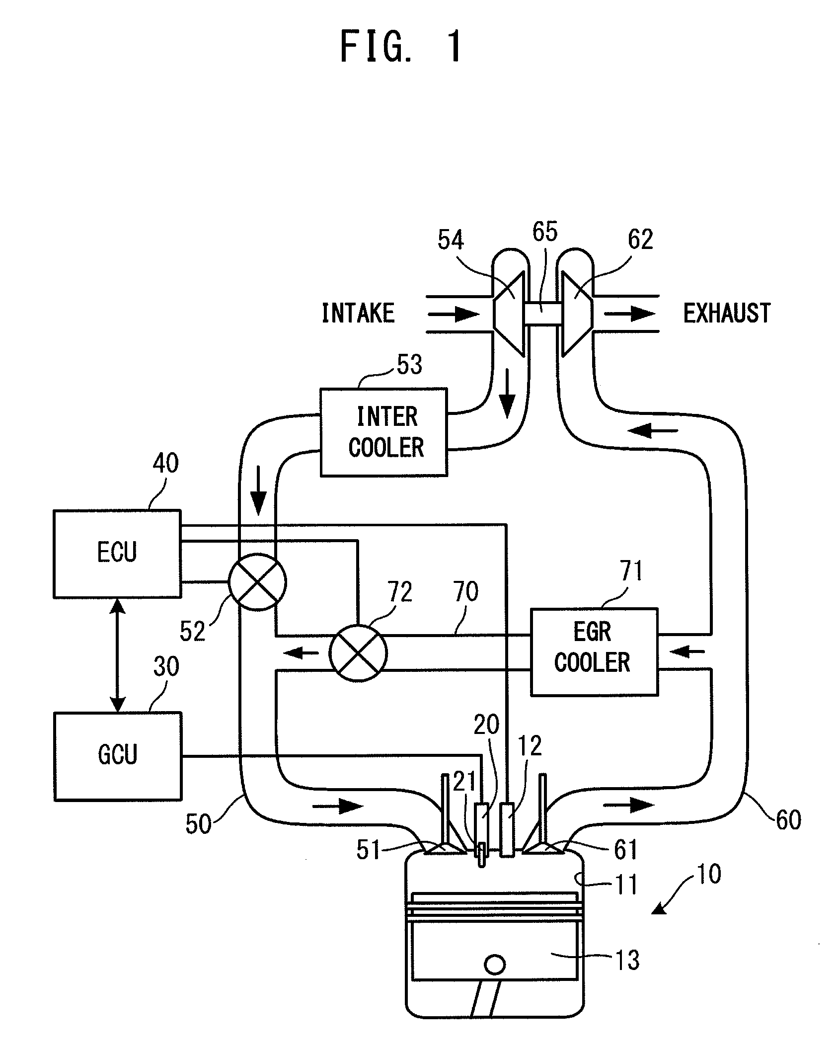
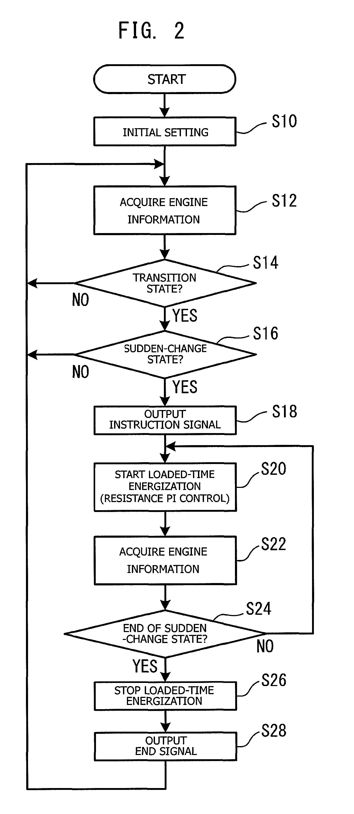

Image

  • Electric current supply control apparatus for glow plug, and glow plug and electric current supply apparatus connected to the glow plug
  • Electric current supply control apparatus for glow plug, and glow plug and electric current supply apparatus connected to the glow plug
  • Electric current supply control apparatus for glow plug, and glow plug and electric current supply apparatus connected to the glow plug

Examples


example 1

[0072]An evaluation test was performed so as to investigate the relationship between the target temperature of the heat generation resistor and the NOX reduction effect. In this evaluation test, an engine for testing (a common-rail-type direct injection 3 L engine equipped with a turbocharger) was first operated in an idling state (about 700 rpm), and, after that, the accelerator pedal was fully depressed. When the accelerator pedal is fully depressed, the speed of the engine for testing reaches about 3000 rpm. The engine was operated under each of the following five conditions, and the concentration of NOX contained in discharged exhaust gas was measured.

Condition 1: No electric current was supplied to the glow plug, and EGR was not performed.

Condition 2: No electric current was supplied to the glow plug, but EGR was performed with the opening of the EGR throttle set to 4.7%.

Condition 3: Electric current was supplied to the glow plug with the target temperature of the heat generati...

example 2

[0074]Next, an evaluation test was carried out so as to investigate the relationship between the temperature rising time of the heat generation resistor of the glow plug (a time required by the heat generation resistor to reach the target temperature from a state where the heat generation resistor is heated to a certain temperature by heat from the engine in an idling state), and an engine speed rising time (a time required by the engine to increase its speed from an idling speed to the maximum engine speed in response to full depression of the accelerator pedal). In this evaluation test, an engine for testing similar to that used in Example 1 was operated in an idling state (in the present example, about 700 rpm). Subsequently, a time between a point in time beginning with full depression of the accelerator pedal, and a point in time when the engine reached its maximum engine speed (an engine speed at the time of full throttle; in the present example, about 3000 rpm) was measured a...

example 3

[0077]Another evaluation test was performed in order to confirm a desired temperature rising time of the heat generation resistor of the glow plug. In this evaluation test, a test similar to that performed in Example 2 was performed with the target temperature of the glow plug set to 1200° C. Specifically, an engine for testing similar to that used in Example 1 was operated in an idling state (in the present example, about 700 rpm). The accelerator pedal was fully depressed, and the concentration of NOX contained in exhaust gas discharged until the engine reached its maximum engine speed (in the present example, about 3000 rpm) was measured. This concentration measurement was performed for eight states (conditions) created by changing the temperature rising time of the heat generation resistor to 1200° C. in 0.5 sec increments within the range of 0.5 sec to 4.0 sec. The EGR amount was adjusted in the same manner as in Example 2; that is, the opening of the EGR throttle was adjusted ...


PUM


Abstract

An electric current supply control apparatus for a glow plug, and glow plug and the electric current supply control apparatus connected to the glow plug. In a transition state in which the load acting on an engine increases such as at the time of acceleration (S14: YES), an instruction signal which instructs increasing of an EGR amount is transmitted to an ECU (S18). Further, electric current is supplied to a heat generation resistor of a glow plug through resistance PI control (S20), whereby the temperature of the heat generation resistor is stably maintained at a target temperature, and stability of combustion is enhanced. Thus, even at the time of acceleration, generation of NOX can be suppressed effectively by increasing the EGR amount without lowering the engine output.

Description

BACKGROUND OF THE INVENTION[0001]1. Field of the Invention[0002]The present invention relates to an electric current supply control apparatus for a glow plug which controls the supply of electric current to a heat generation resistor of a glow plug mounted to an engine, and to a glow plug and electric current supply control apparatus connected to the glow plug.[0003]2. Description of the Related Art[0004]Conventionally, a technique has been known called exhaust gas recirculation (hereinafter, also referred to as “EGR”) in which exhaust gas discharged from an engine of an automobile is partially returned to the intake side and reintroduced into the engine. When EGR is performed, the concentration of oxygen within air taken into the engine decreases, whereby combustion of fuel becomes less explosive. In addition, in the intake air, the concentration of carbon dioxide, which has a higher heat capacity than oxygen, increases. Thus, an increase in combustion temperature is suppressed. As...

Claims


Application Information

Patent Timeline
Patent Type & Authority Patents(United States)
IPC IPC(8): F02P19/02F02P19/00
CPCF02D41/005F02D41/064F02P19/025F02P19/026F02D41/10F02D2041/1409Y02T10/47Y02T10/40
Inventor OKINAKA, MANABUNAKAMURA, TOSHIYUKI
Owner NGK SPARK PLUG CO LTD
Learn More