
Optical devices with built-in isolators

Active Publication Date: 2013-01-08
ALLIAN FIBER OPTIC PROD INC
View PDF2 Cites 14 Cited by
  • Summary
  • Abstract
  • Description
  • Claims
  • Application Information

AI Technical Summary

Benefits of technology

The present invention improves the designs of optical devices for adding, dropping, and multiplexing signals. It uses an isolator to minimize noise and isolate residual signals, resulting in high isolation. The devices are small, have a wide range of wavelengths, and are easy to manufacture. The technical effect of the invention is to improve the performance and cost-effectiveness of optical devices.

Problems solved by technology

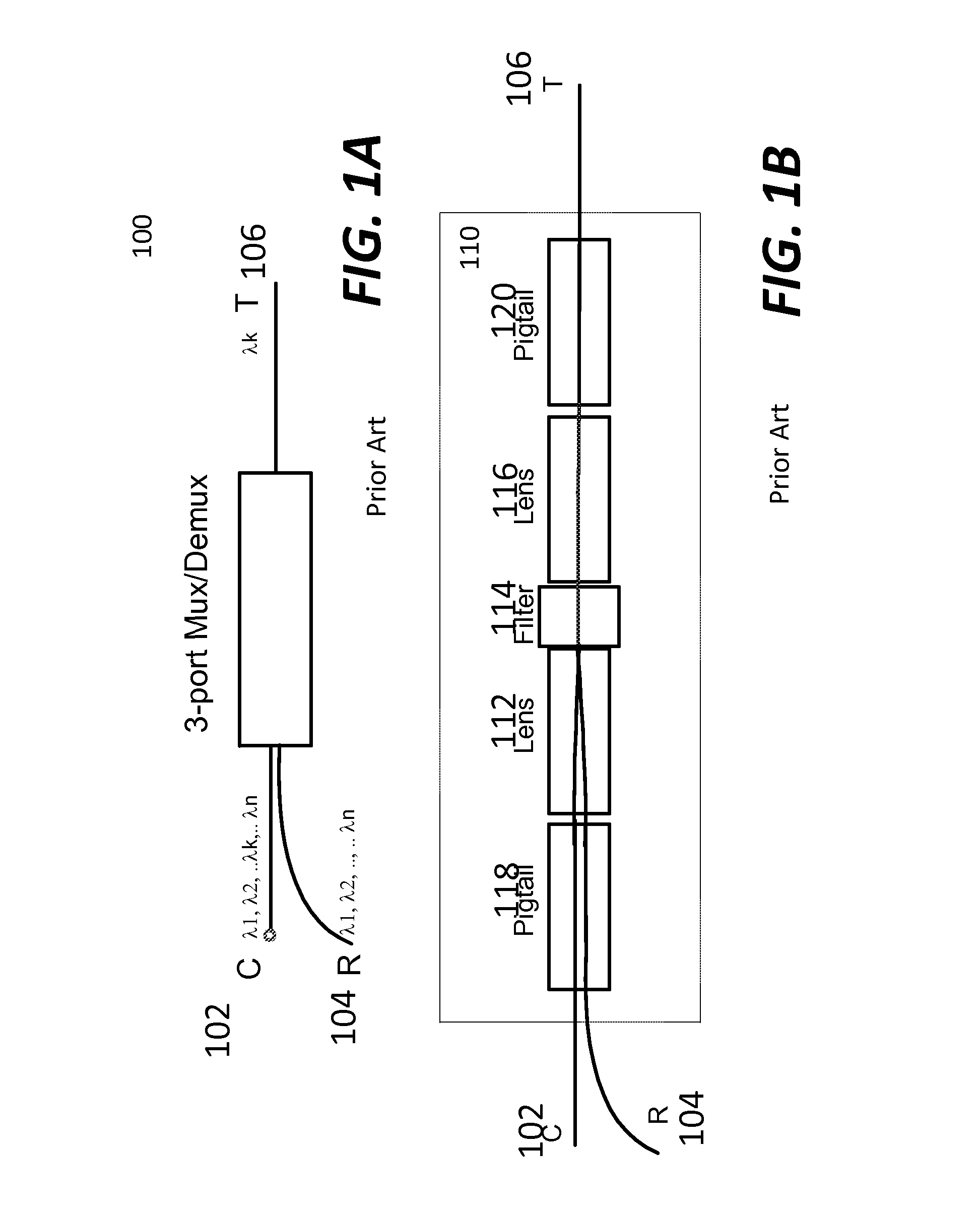
In most occasions, however, each of the ports may reflect a certain level of signal, referred to as a noise.
This back reflection signal or noise can cause signal fluctuation.
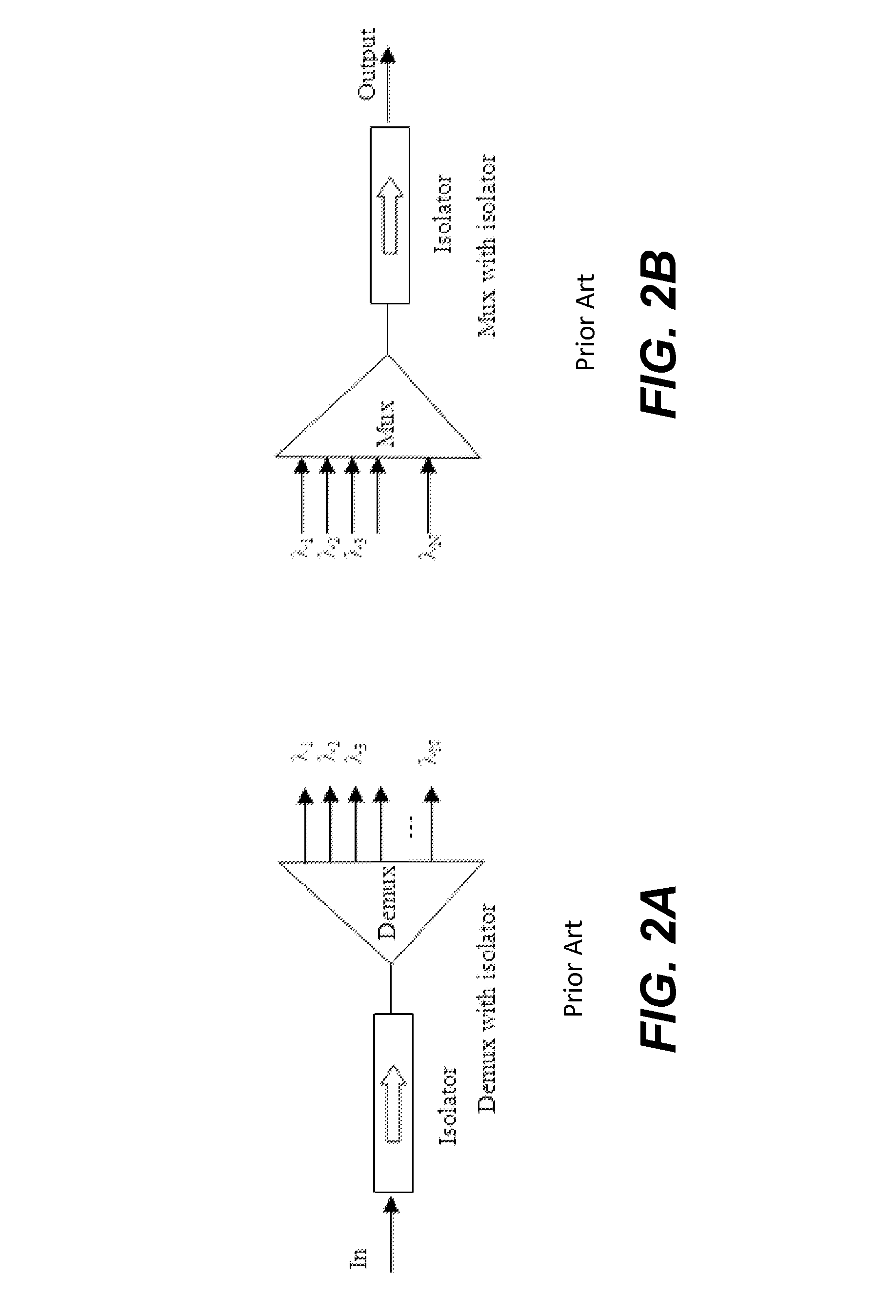
The combination of the isolator and a multiplexer or a demultiplexer causes some problems.
One of the noticeable problems is a relatively large space required to accommodate these two individual parts.
Another one is the complicated procedures involved to optically align these two parts, thus incurring additional labels and costs in real installations.

Method used


Image

  • Optical devices with built-in isolators
  • Optical devices with built-in isolators
  • Optical devices with built-in isolators

Examples


Embodiment Construction

[0031]The detailed description of the present invention is presented largely in terms of procedures, steps, logic blocks, processing, or other symbolic representations that directly or indirectly resemble the operations of optical devices or systems that can be used in optical networks. These descriptions and representations are typically used by those skilled in the art to most effectively convey the substance of their work to others skilled in the art.

[0032]Reference herein to “one embodiment” or “an embodiment” means that a particular feature, structure, or characteristic described in connection with the embodiment can be included in at least one embodiment of the invention. The appearances of the phrase “in one embodiment” in various places in the specification are not necessarily all referring to the same embodiment, nor are separate or alternative embodiments mutually exclusive of other embodiments.

[0033]Referring now to the drawings, in which like numerals refer to like parts...


PUM


Abstract

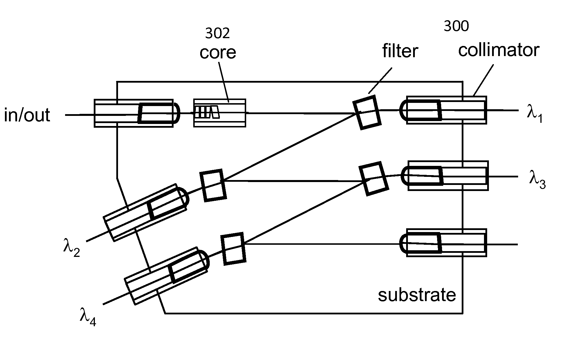
New designs of optical devices, particularly for adding or dropping a selected wavelength or a group of wavelengths as well as multiplexing a plurality of signals into a multiplexed signal or demultiplexing a multiplexed signal into several signals are disclosed. According to one aspect of the present invention, an isolator core is built into the optical devices to stop a reflected signal from an optical file in the optical devices. As a result, the optical devices are amenable to small footprint, broad operating wavelength range, enhanced impact performance, lower cost, and easier manufacturing process.

Description

BACKGROUND OF THE INVENTION[0001]1. Field of the Invention[0002]The invention is generally related to the area of optical communications. More particularly, the invention is related to optical wavelength multiplexing and add / drop devices with high reflection channel isolation and the method for making the same.[0003]2. The Background of Related Art[0004]The future communication networks demand ever increasing bandwidths and flexibility to different communication protocols. Fiber optic networks are becoming increasingly popular for data transmission due to their high speed and high capacity capabilities. Wavelength division multiplexing (WDM) is an exemplary technology that puts data from different sources together on an optical fiber with each signal carried at the same time on its own separate light wavelength. Using the WDM system, many separate wavelengths or channels of data can be multiplexed into a light stream transmitted on a single optical fiber. To take the benefits and ad...

Claims


Application Information

Patent Timeline
IPC IPC(8): H04J14/02
CPCH04J14/02
Inventor WANG, DAOYILI, YAOZHOU, ANDY
Owner ALLIAN FIBER OPTIC PROD INC
Learn More