
Washer pump

a technology of washing pump and impeller, which is applied in the field of pumps, can solve the problems of reducing the cleaning action of the washing system, less effective spraying of the headlamp or windshield, etc., and achieves the effects of improving cold performance, increasing impeller clearance, and improving p-q performan

Active Publication Date: 2013-01-08
DLHBOWLES INC
View PDF2 Cites 10 Cited by
  • Summary
  • Abstract
  • Description
  • Claims
  • Application Information

AI Technical Summary

Benefits of technology

The present invention is a new washer pump assembly that improves the performance of automotive windshield washing systems in cold weather conditions. The pump has a higher operating pressure and flow rate compared to typical pumps, resulting in better spray onto the windshield and headlamp. The pump's improved performance is achieved through a newly developed impeller and casing design that enhances the pump's pressure-flow rate curve. The casing has a slight spiral deviation and a circular profile for most of a circle, providing constant clearance with the impeller and increasing impeller clearance towards the pump's fluid outlet. The pump assembly is more efficient, consuming less energy and providing better performance with colder fluids.

Problems solved by technology

With reduced pump pressure, it was observed that nozzles operated at lower pressure in cold weather, leading to less effective spray onto the headlamp or windshield and reduced cleaning action for the washing system.

Method used


Image

  • Washer pump
  • Washer pump
  • Washer pump

Examples


Embodiment Construction

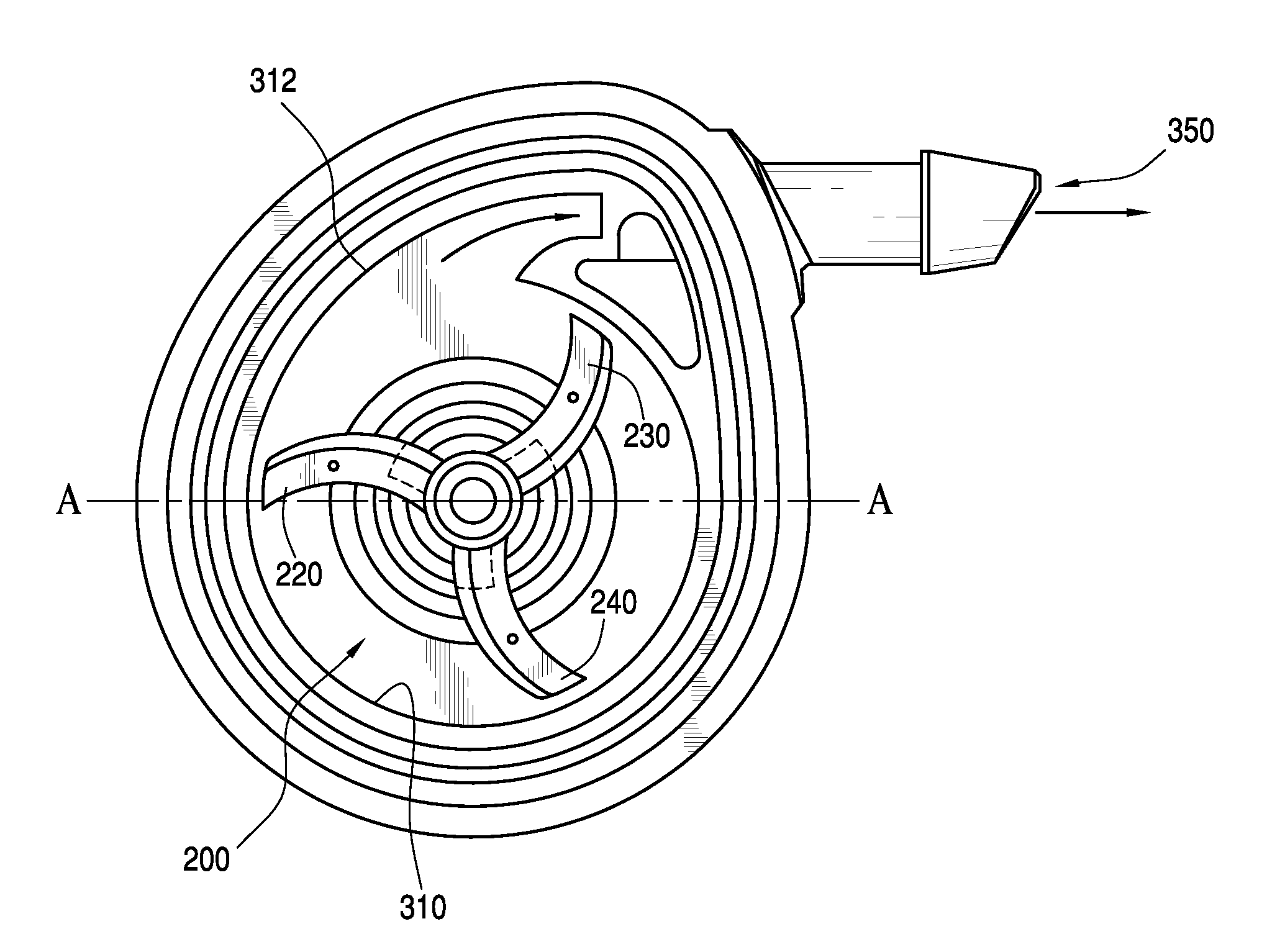
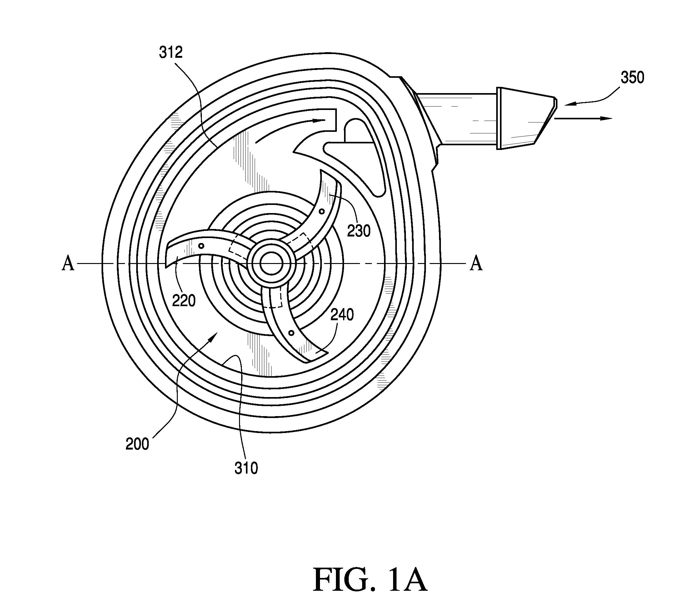
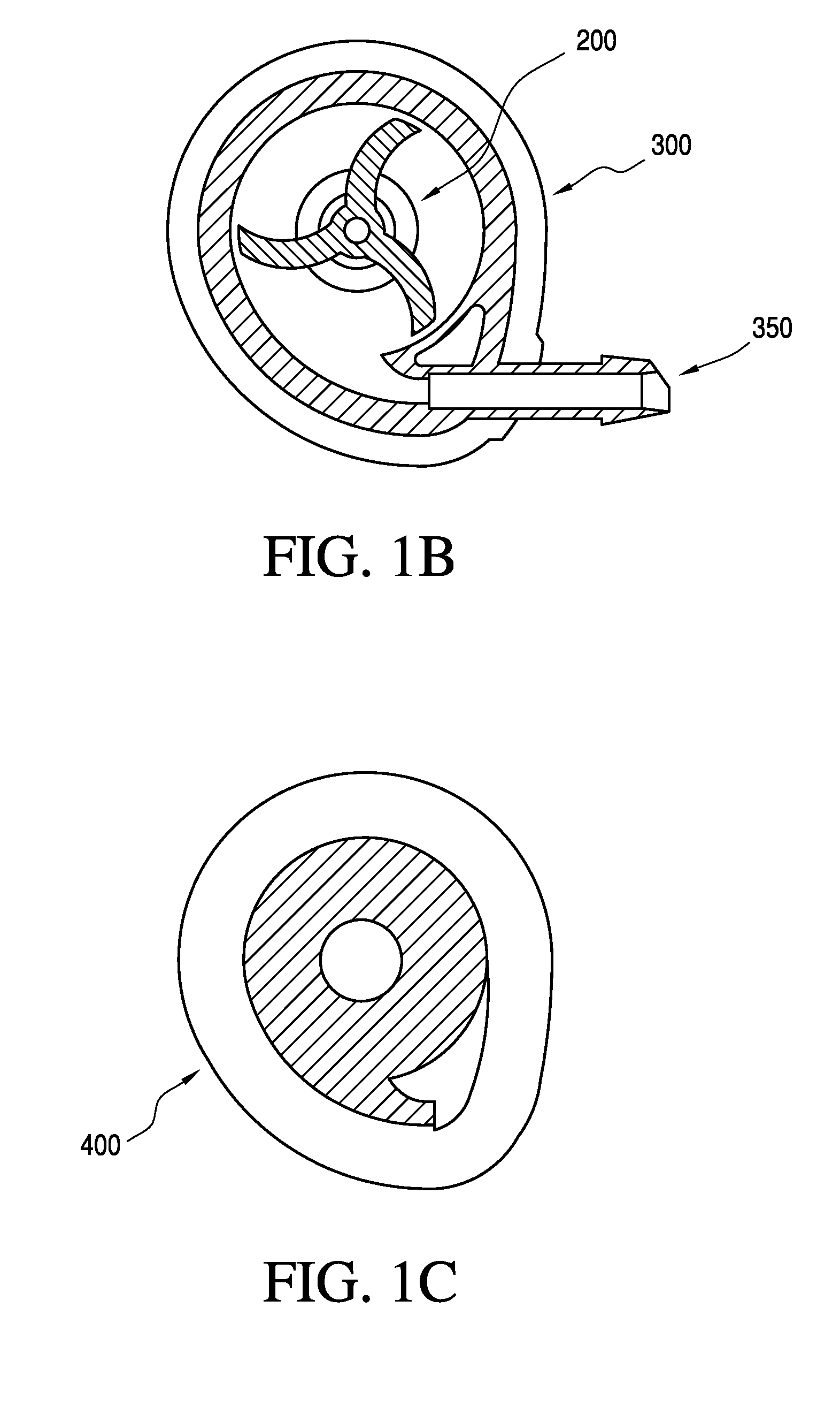
[0041]Referring to FIGS. 1A-3B, a first embodiment of the pump assembly 100 of the present invention includes an impeller 200 and volute casing 300 designed to provide high operating pressures (“P”) and flow rates (“Q”) with low energy usage. Impeller 200, as best seen in FIGS. 2A-2D has a central shaft 210 carrying a plurality (preferably three) radially projecting curved primary vanes 220, 230 and 240, and each primary vane also has a twist along its length (in the radial direction). Secondary impeller vanes 224, 234, and 244 each define triangular connecting fillet-like wall segments connecting each primary vane to the sidewall surface of impeller shaft 210. The secondary vanes can also have a twist similar to the primary vanes. As best seen in FIGS. 1A and 3A, volute 300 has a slight spiral deviation so that the pump chamber's interior sidewall 310 flares away from the swept area of the impeller's primary vanes 220, 230 and 240 to define a fluid outlet 350 that contributes to hi...


PUM


Abstract

An enhanced pump assembly includes an impeller and volute casing designed to provide high operating pressures (“P”) and flow rates (“Q”) with low energy usage. The impeller has a central shaft carrying radially projecting curved primary vanes, and each primary vane also has a twist in the radial direction. Secondary impeller vanes define triangular connecting fillet-like wall segments connecting each primary vane to the impeller shaft. The casing of the pump has a slight spiral deviation so that the pump chamber's radial sidewall flares away from the swept area of the impeller's vanes to define a fluid outlet that contributes to higher P-Q performance, especially when pumping colder fluids.

Description

[0001]This application claims priority benefit to commonly owned patent application No. 61 / 060,112 filed on Jun. 9, 2008, the entire disclosure of which is incorporated herein by reference.BACKGROUND OF THE INVENTION[0002]1. Field of the Invention[0003]The present invention relates to pumps configured to spray washer fluid onto an automotive windshield, headlamp or other surface, to assist a cleaning or wiping operation.[0004]2. Discussion of Related Art[0005]Automotive windshield washer systems now in use in automotive vehicles generally include at least one windshield wiper adapted to be driven by a drive unit to move back and forth across the windshield, a windshield washer pump having an inlet and an outlet, at least one jetting nozzle generally carried on the automobile's hood and fluid-connected with the outlet of the washer pump for spraying a cleaning fluid onto the windshield, and a container or tank for accommodating a quantity of the cleaning or washing fluid and fluid-co...

Claims


Application Information

Patent Timeline
Patent Type & Authority Patents(United States)
IPC IPC(8): F04D29/00
CPCF04D29/242F04D29/426
Inventor GOPALAN, SHRIDHARROMACK, ALANZHAO, CHUNLING
Owner DLHBOWLES INC
Learn More