
Electrophotographic photoreceptor and image forming apparatus provided with the same

a photoreceptor and photoreceptor technology, applied in the direction of electrographic process, instruments, corona discharge, etc., can solve the problems of sensitivity, durability, image defects, uneven densities, etc., and achieve the effect of reducing the variation in sensitivity and good image characteristics

Active Publication Date: 2012-12-25
SHARP KK
View PDF11 Cites 0 Cited by
  • Summary
  • Abstract
  • Description
  • Claims
  • Application Information

AI Technical Summary

Benefits of technology

The solution provides a photoreceptor with reduced sensitivity variation and excellent image characteristics in both low-temperature / low-humidity and high-temperature / high-humidity environments, maintaining stable electric characteristics and preventing image defects like black dots and fogging.

Problems solved by technology

Although photoreceptors (referred to also as an “inorganic photoreceptor”) provided with a photosensitive layer containing an inorganic photoconductive material as its major component have been widely used so far, they have a drawback in any of heat resistance, storage stability, toxicities to human bodies and environments, sensitivity, durability, occurrence of image defects, productivity, production costs, and the like and no photoreceptor which satisfies all of these characteristics has been obtained.
When a photosensitive layer is directly formed on a conductive support by application in the production of an organic photoreceptor, the photosensitive layer is easily affected by the surface of the conductive support and it is therefore difficult to form a uniform film having a uniform thickness.
Therefore, there is a problem that the film thickness becomes uneven, causing various image defects and uneven densities.
Therefore, when an electric field is applied by electrification, charges generate at a part of the charge generating material and the potential is locally dropped at a place near the charge generating material, giving rise to a problem of the generation of fogging on white paper or gray parts in reverse developing.
This problem is particularly significant in a high-temperature and high-humidity environment.
However, even if such an intermediate layer is formed, since these alcohol-soluble resins are largely varied in resistance according to circumstances such as temperature and humidity, there is a problem that the potential is largely changed with environmental variation, and also that there are image defects such as generation of black dots and memories and uneven densities, though good electric characteristics and image quality are obtained in a usual environment.
However, the polyamide resin used for the intermediate layer has drawbacks that it is hardly soluble in a solvent, tends to cause uneven coating, deteriorates the dispersibility of titanium oxide, easily causing the solution to be clouded, and is increased in the accumulation amount of residual potential in a high-temperature and high-humidity condition, though it is affected little by the influence of environmental variations and has a small water absorption coefficient.
Therefore, the aforementioned proposals in the conventional techniques are insufficient as to the characteristics of the electrophotographic photoreceptor and it is desired to develop an electrophotographic photoreceptor having more excellent characteristics.

Method used


Image

  • Electrophotographic photoreceptor and image forming apparatus provided with the same
  • Electrophotographic photoreceptor and image forming apparatus provided with the same
  • Electrophotographic photoreceptor and image forming apparatus provided with the same

Examples


production example 1

[0181]A polyamide resin of the present invention was produced as will be explained below.

[0182]A higher unsaturated fatty acid methyl ester (400 g) containing 72% of methyl oleate, 18% of methyl linoleate and 10% of methyl hexadecanoate was used as a raw material and a dimerization reaction was carried out at 230° C. for 5 hours by using 17% of activated white earth as a catalyst. Next, an unreacted fatty acid methyl ester fraction and an isomerized fatty acid methyl ester fraction were removed from the resulting product by vacuum distillation (230° C. / 1 torr) and the residue was subjected to molecular distillation (230° C. / 0.1 torr) to give dimethyl dicarboxylate (200 g) as a distillate and trimethyl tricarboxylate (50 g) as a distillation residue.

[0183]Then, the obtained dimethyl dicarboxylate and trimethyl tricarboxylate were mixed at a ratio of 7 / 3 and 2% of a Ni catalyst was added to the mixture, which was then made to undergo a hydrogenating reaction under a hydrogen pressure ...

production example 2

[0186]A polyamide resin (180 g) was obtained in the same manner as in Production Example 1 except that a compound obtained by methyl-esterifying commercially available HARIDIMER 200 (manufactured by Harima Chemicals, Inc.) (200 g) was used in place of dimethyl dicarboxylate used in Production Example 1 (a:b=1.0:1.0).

production example 3

[0187]A polyamide resin (190 g) was obtained in the same manner as in Production Example 1 except that a solution (1 L) obtained by methyl-esterifying commercially available EMPOL 1018 (manufactured by Cognis Corporation) (200 g) and dissolving 1.0 carboxyl group equivalent (220 g) of the esterified product in methanol such that its concentration became 25% and a solution (2 L) obtained by dissolving 1.0 amino group equivalent (26 g) of piperazine in methanol such that its concentration became 50% were used (a:b=2.0:0.5).


PUM

PropertyMeasurementUnit
number average primary particle diameteraaaaaaaaaa
reaction temperatureaaaaaaaaaa

Abstract

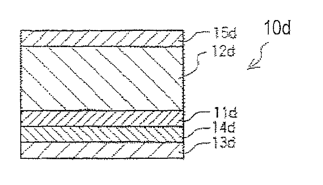
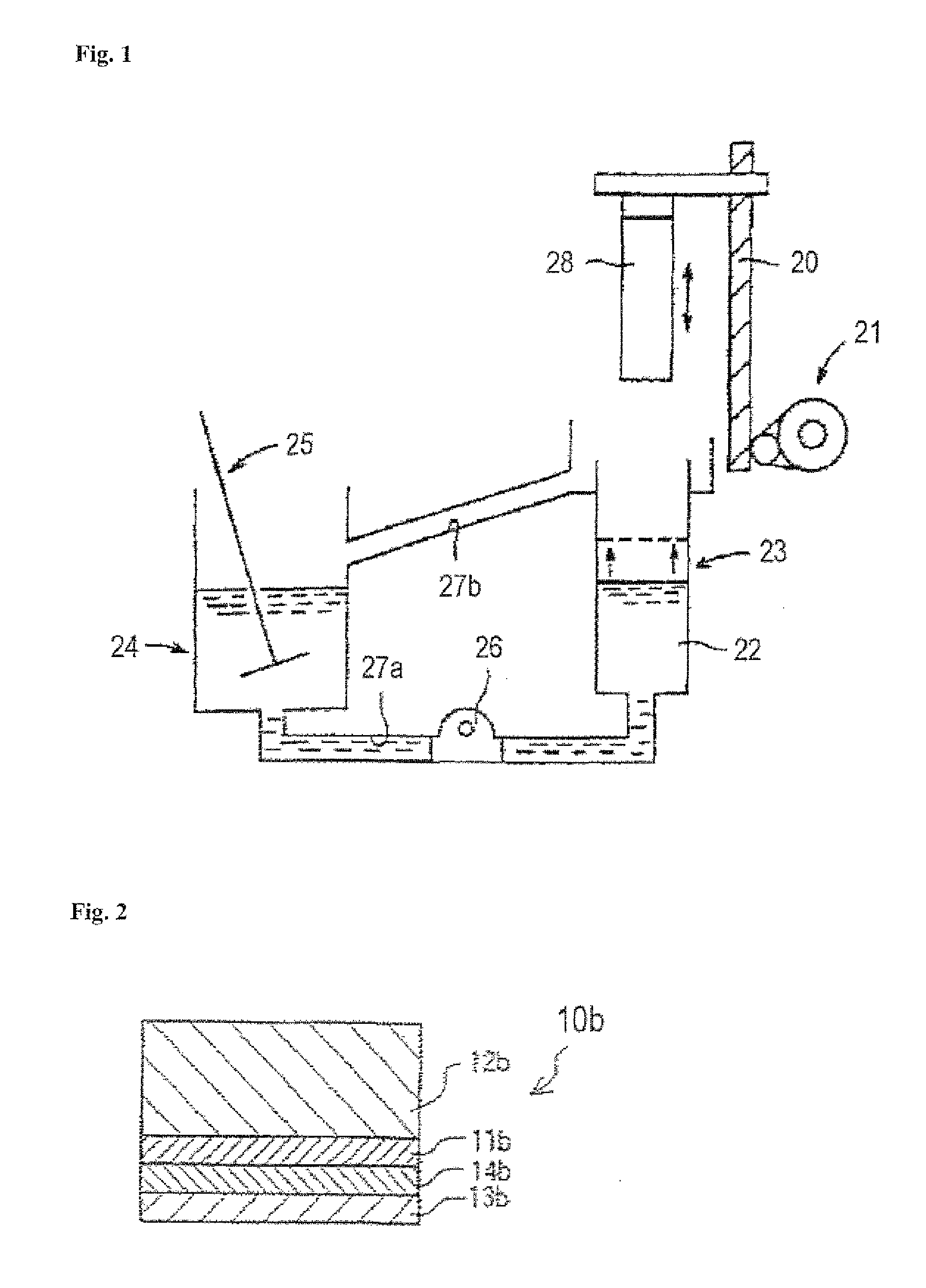
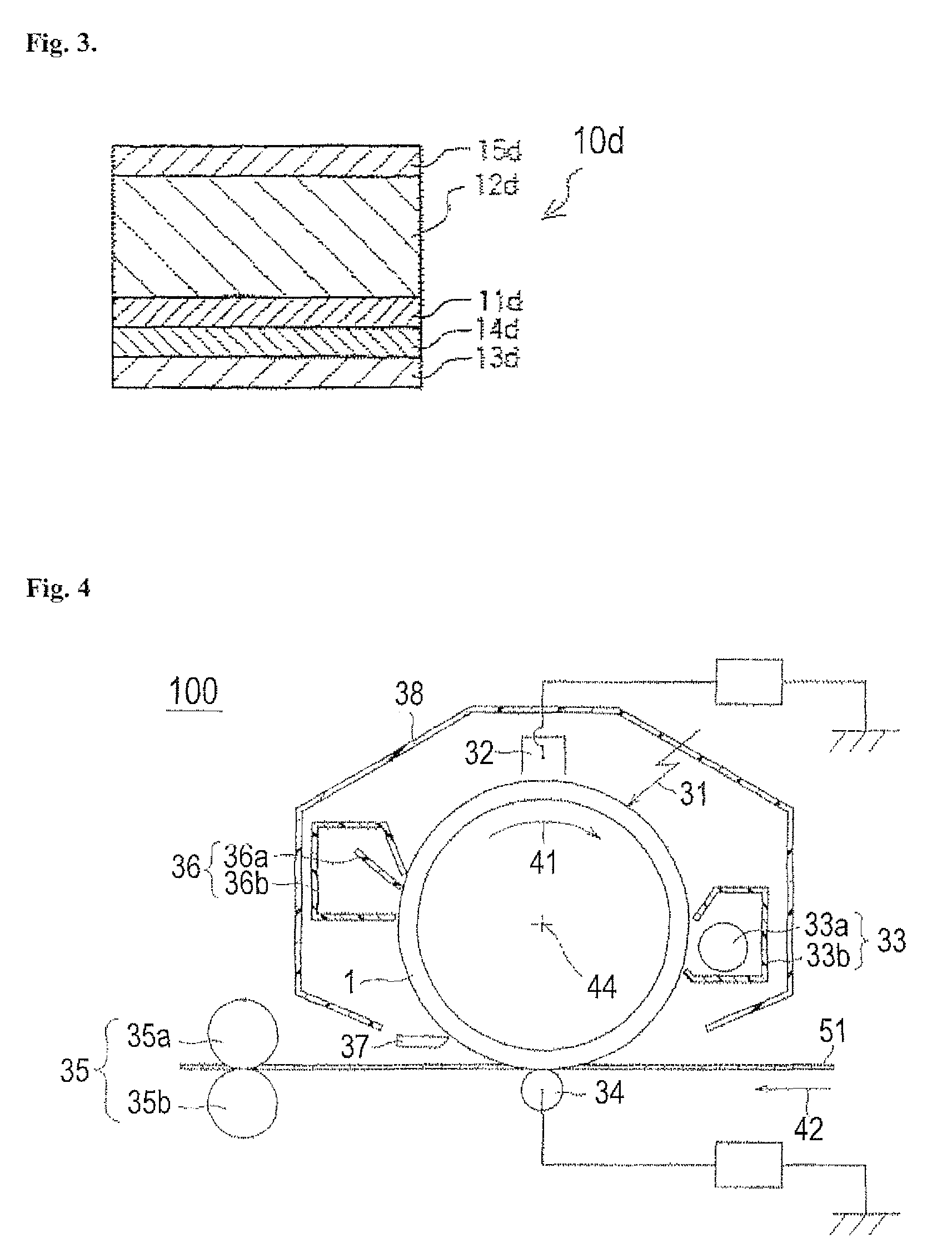
An electrophotographic photoreceptor comprising: a conductive support, a photosensitive layer and an intermediate layer interposed between the conductive support and the photosensitive layer, wherein the intermediate layer contains metal oxide microparticles surface-treated with silicon dioxide anhydride and a binder resin; and the binder resin contains a polyamide resin containing a piperazine-based compound.

Description

CROSS-REFERENCE TO RELATED APPLICATION[0001]This application is related to Japanese Patent Application No. 2009-230556 filed on 2 Oct. 2009, whose priority is claimed under 35 USC §119, and the disclosure of which is incorporated by reference in its entirety.BACKGROUND OF THE INVENTION[0002]1. Field of the Invention[0003]The present invention relates to an electrophotographic photoreceptor (hereinafter also referred to as a “photoreceptor” which is provided with an intermediate layer containing a polyamide resin having a specified structure and metal oxide microparticles, is reduced in the variation in sensitivity in a low-temperature and low-humidity condition and can attain good image characteristics even after being used repeatedly, and to an image forming apparatus provided with the photoreceptor.[0004]More specifically, the present invention relates to an electrophotographic photoreceptor in which the intermediate layer contains a polyamide resin which is a condensate of a pipe...

Claims


Application Information

Patent Timeline
Patent Type & Authority Patents(United States)
IPC IPC(8): G03G5/00
CPCG03G5/0638G03G5/075G03G5/076G03G5/142G03G5/144G03G5/14765G03G15/751G03G2215/00957G03G5/0766
Inventor KATAYAMA, SATOSHITORIYAMA, KOICHISUGIMURA, HIROSHI
Owner SHARP KK
Learn More