Developing apparatus
A developing device and developing agent technology, applied in the direction of instruments, electrical recording process equipment using charge patterns, optics, etc., can solve the problems that hinder the miniaturization of the image forming device as a whole and hinder the miniaturization of the developing device 101, etc.
- Summary
- Abstract
- Description
- Claims
- Application Information
AI Technical Summary
Problems solved by technology
Method used
Image

Examples
Embodiment 1
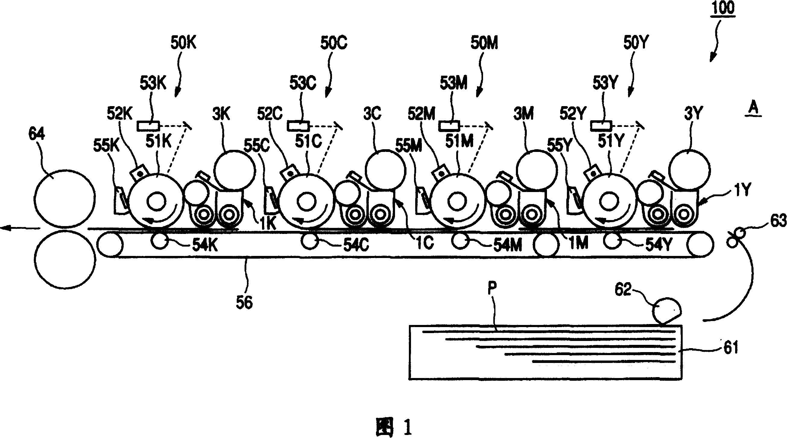
[0036] FIG. 1 shows a schematic cross-sectional view of an example of an image forming apparatus 100 to which the present invention is applied. The image forming apparatus 100 of this embodiment has four image forming sections 50Y, 50M, 50M, 50M, and 50C, 50K color electrophotographic image forming apparatus. Fig. 1: The image forming apparatus 100, based on the image information signal from an external host such as a personal computer communicably connected to the apparatus main body A, or from a document reading device attached to or communicably connected to the apparatus main body A, can be A color image is formed on a recording material P such as recording paper, OHP sheet, cloth, or the like.
[0037] First, the overall operation of the image forming apparatus 100 will be described. In the twentieth embodiment, the image forming units 50Y, 50M, 50C, and 50K included in the image forming apparatus 100 basically have the same configuration, and the colors of the images f...
experiment example 1
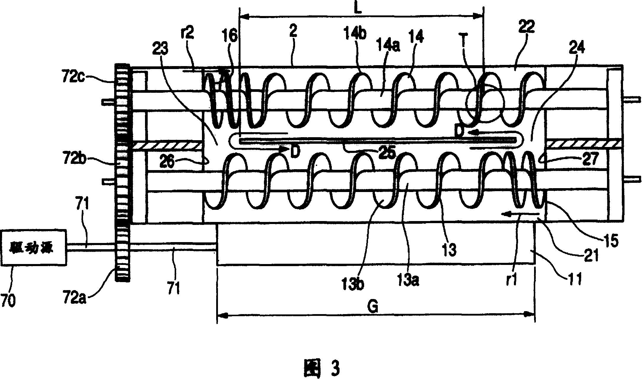
[0073] In this experiment, 1 g of toner was supplied at the toner supply position T, and the charged amount of the supplied toner at the first communicating portion 23 was measured. Furthermore, in this experiment, the inclination of the stirring chamber 22 to the horizontal direction (the upward gradient from the second communicating portion 24 side to the first communicating portion 23 side) (hereinafter simply referred to as “inclination”) θ is taken as 0° (horizontal), 1°, 2°, 5°, 10°, 12°. Each tested developing device had the same configuration except for this inclination.
[0074] The experimental results are shown in Table 1. For the chargeability of the toners in Table 1, the chargeability of 3000 toners was measured with an E-Spart analyzer manufactured by Hosokawa Micron Co., Ltd., and it was good (○) when substantially all the toners were negative polarity. , when the toner was not triboelectrically charged (the charge amount was 0) or was positively polarized, i...
Embodiment 2
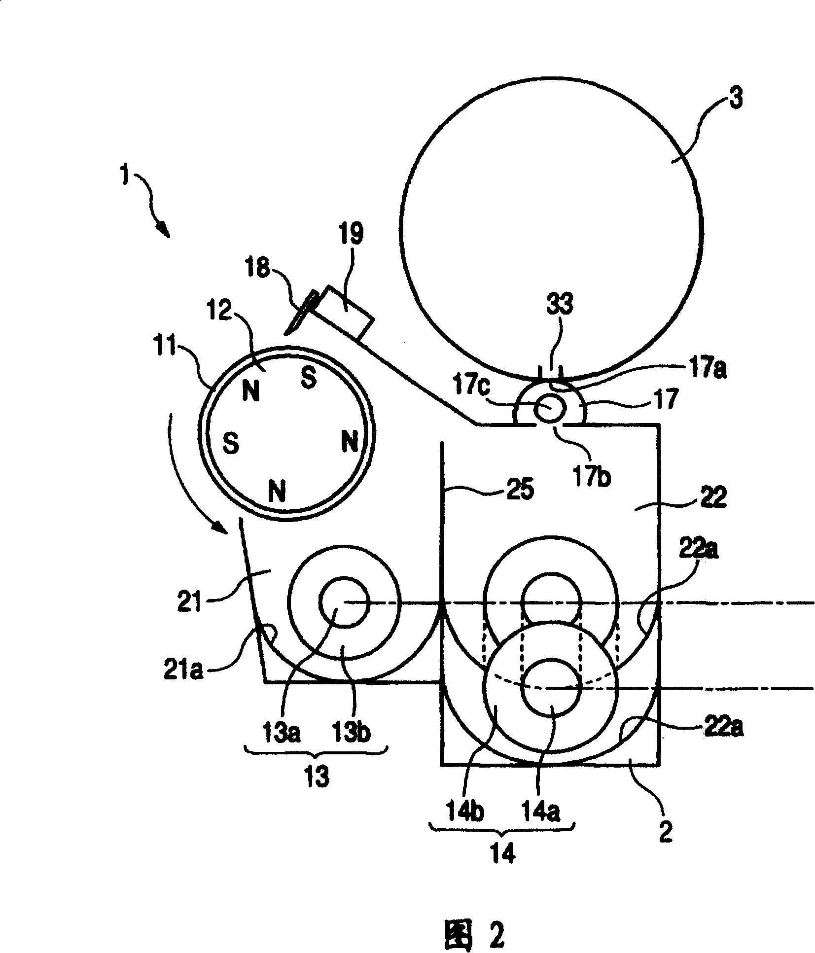
[0102] Next, another embodiment of the present invention will be described with reference to FIG. 5 . In this embodiment, the present invention is embodied in an image forming apparatus equipped with the same developing device as in Embodiment 1, and the basic configurations of the developing device and the image forming apparatus are the same as those in Embodiment 1. Therefore, elements having the same or equivalent configurations and functions as those of Embodiment 1 are given the same reference numerals, and detailed description thereof will be omitted.
[0103] In the developing device 1 of this embodiment, as shown in FIG. 5, like the developing device 1 described in Embodiment 1, the bottom surface 22a of the stirring chamber 22 has an inclination of 5° with respect to the horizontal direction (from the side of the second communicating portion 24). 1st connecting part 23 side uphill gradient).
[0104] Moreover, in this embodiment, at the first communicating portion 2...
PUM
 Abstract
Description
Claims
Application Information
 - R&D
- Intellectual Property
- Life Sciences
- Materials
- Tech Scout
- Unparalleled Data Quality
- Higher Quality Content
- 60% Fewer Hallucinations
Browse by: Latest US Patents, China's latest patents, Technical Efficacy Thesaurus, Application Domain, Technology Topic, Popular Technical Reports.
© 2025 PatSnap. All rights reserved.Legal|Privacy policy|Modern Slavery Act Transparency Statement|Sitemap|About US| Contact US: help@patsnap.com