
Timer controlled, short and open circuit fault detection with slew-rate boosted output driver

a driver and output technology, applied in the direction of amplifier protection circuit arrangement, amplifier with semiconductor devices/discharge tubes, amplifiers, etc., can solve the problems of driver output stage, unintended short circuit and open circuit, and the approaching stage output voltage, so as to reduce the settling time of the circuit

Active Publication Date: 2012-12-11
MAXIM INTEGRATED PROD INC
View PDF2 Cites 19 Cited by
  • Summary
  • Abstract
  • Description
  • Claims
  • Application Information

AI Technical Summary

Benefits of technology

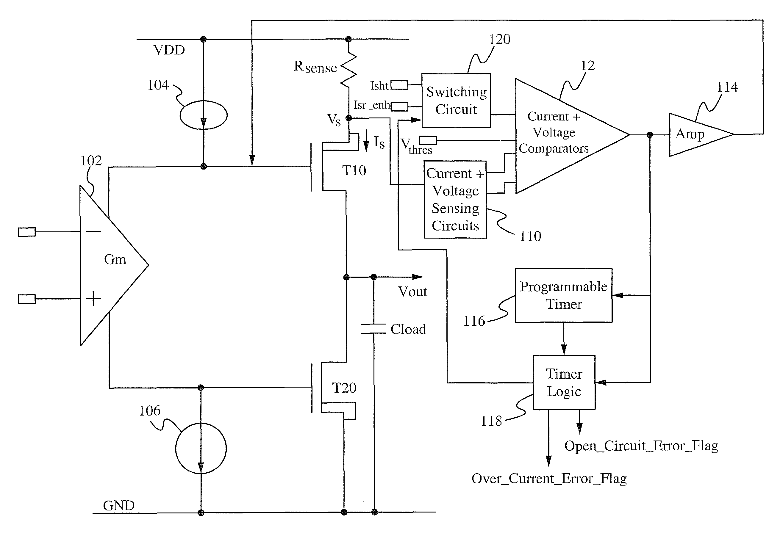
[0015]Embodiments of a driver circuit includes a programmable timer and timer logic to adjust a slew rate delay period used to accommodate slewing current when charging or discharging a load capacitor, and to increase the current limit during the slew rate delay period by selecting a larger input current reference value. Increasing the current limit provides for a faster settling time. The value of each input current reference value can be programmed. The programmable timer and the timer logic can be configured to coordinate the slew rate delay period and the selected input current reference value. The slew rate delay period can be adjusted based on which input current reference value is applied. An open circuit condition can also be determined, and the programmable timer and timer logic can be further configured to delay the generation of an open circuit error flag in order to accommodate short duration events where the output voltage is the same, or in some embodiments close to, the supply voltage.
[0018]In yet another aspect, a circuit is disclosed that includes an output driver circuit having a driver current; a load capacitor coupled to the driver circuit to receive the driver current; and a feedback circuit coupled to the driver circuit, wherein the feedback circuit is configured to determine an over-current condition in the driver circuit and to limit the driver current to a limit current value upon determination of the over-current condition. The feedback circuit includes a current sensing circuit configured to sense the driver current; a switching circuit configured to receive a plurality of input current reference values as a plurality of inputs, and to output a selected input current reference value from the plurality of input current reference values in response to a selection signal, wherein the selected input current reference value is used to determine the over-current condition and the limit current value, thereby enabling adjustment of the limit current value during the over-current condition according to the selected input current reference value; a current comparator coupled to the current sensing circuit to receive the sensed driver current as a first input and coupled to the switching circuit to receive the selected input current reference value as a second input, the current comparator outputs a comparison signal indicating that the over-current condition is present if the driver current is equal to or greater than the selected input current reference value; a programmable timer coupled to the current comparator; and a timer logic circuit configured to generate the selection signal and output the selection signal to the switching circuit, wherein the timer logic circuit and the programmable timer are configured to delay generation of an error flag in response to the over-current condition according to a slew rate delay period, the programmable timer is configured to vary the slew rate delay period according to a loading condition applied to the load capacitor. The limit current is a slewing current of the load capacitor. The limit current value can be increased during the over-current condition, thereby decreasing a settling time of the circuit. The limit current can be increased during the slew rate delay period by selecting a larger input current reference value from the plurality of input current reference values. The selected input current reference value can be determined according to the slew rate delay period. Each of the plurality of input current reference values can be programmable. The feedback circuit can be further configured to determine an over-voltage condition in the driver circuit, and the programmable timer and the timer logic can be further configured to delay generation of an over-voltage error flag in response to the over-voltage condition.

Problems solved by technology

Typical error conditions include unintended short circuits and open circuits.
If the cable becomes shorted to a power supply of the amplifier or to ground, an over-current condition results at the driver output stage.
If the cable open circuits, such as a broken or severed cable, the controlled driver current can not be supplied to the load, which results in a driver stage output voltage approaching the supply voltage, in which case the controlling signal will be lost.
Left unresolved, a short circuit results in increasing current Is until breakdown occurs.
One such condition results from the circuit's inability to differentiate between a real short circuit condition and a normal heavy slewing condition that occurs when charging the load capacitor Cload to the output voltage Vout.
This problem is intensified with high capacitive loading, such as capacitive loading up to 100 uF, as a larger load capacitor generates a larger slewing current.
As such, false shorts may result from normal slewing conditions, or the charging of a large load capacitor.
An open circuit condition may result in the driver circuit losing the control signal.
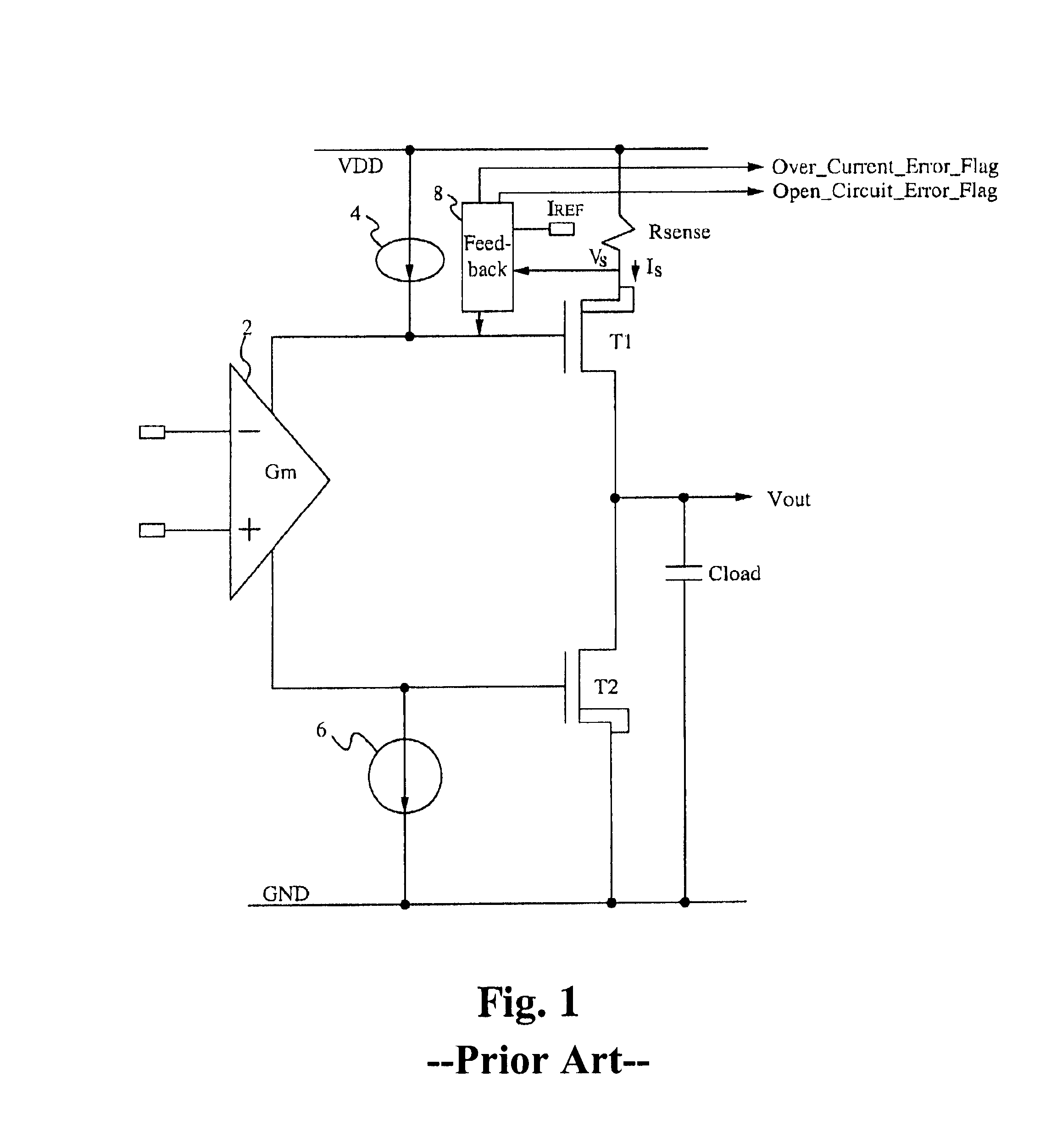
In general, the fault detection circuit of FIG. 1 inappropriately determines certain short duration events as fault conditions.
The fault detection circuit can not differentiate between the normal slewing current when the load capacitor is charging versus an actual short circuit condition.
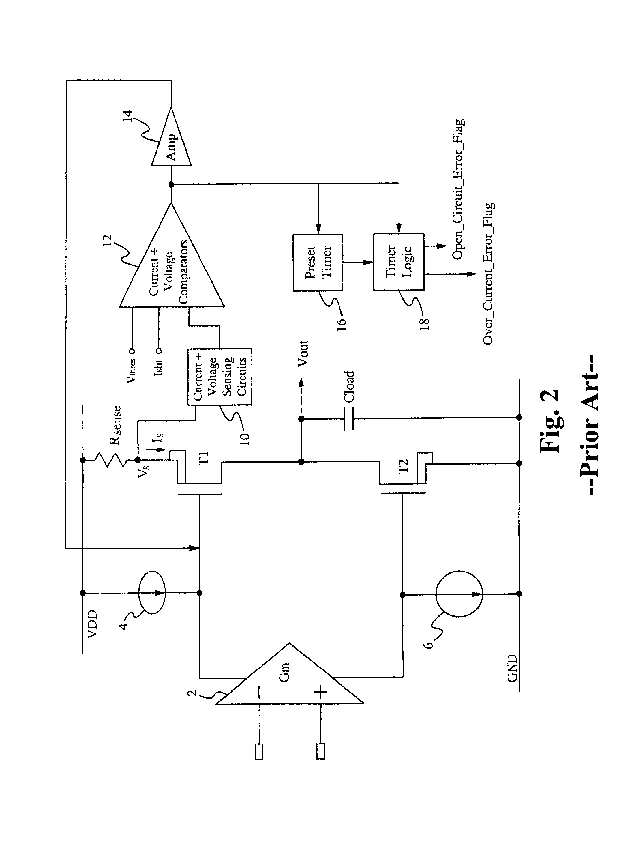
Although the circuit of FIG. 2 allows for such short duration events before issuing an over-current error flag, the current Is is still limited to the short circuit limit current during this time period.
In addition to inappropriately determining short circuit conditions, the fault detection circuit of FIG. 1 also inappropriately determines certain conditions as open circuit fault conditions, such as when the output voltage Vout is dynamically switched to a voltage level that approaches the supply voltage VDD, which results in a longer time period to discharge the load capacitor to a controlled level.
This can result in a false open circuit error flag.
In addition to generating false error flags, the fault detection circuits of FIGS. 1 and 2 do not have the ability to boost the slewing current beyond the short circuit limit current.
In particular, the slewing current is limited by the short circuit limit current when driving large capacitive loads.
This results in slower settling time for the circuit.
In some applications, loads coupled to the output capacitor Cload have response time requirements that would be adversely affected by a slower settling time.
Systems with energy storage elements cannot respond instantaneously and exhibit transient responses when subjected to inputs or disturbances.

Method used


Image

  • Timer controlled, short and open circuit fault detection with slew-rate boosted output driver
  • Timer controlled, short and open circuit fault detection with slew-rate boosted output driver
  • Timer controlled, short and open circuit fault detection with slew-rate boosted output driver

Examples


Embodiment Construction

[0023]Embodiments of the present application are directed to a driver circuit. Those of ordinary skill in the art will realize that the following detailed description of the driver circuit is illustrative only and is not intended to be in any way limiting. Other embodiments of the driver circuit will readily suggest themselves to such skilled persons having the benefit of this disclosure.

[0024]Reference will now be made in detail to implementations of the driver circuit as illustrated in the accompanying drawings. The same reference indicators will be used throughout the drawings and the following detailed description to refer to the same or like parts. In the interest of clarity, not all of the routine features of the implementations described herein are shown and described. It will, of course, be appreciated that in the development of any such actual implementation, numerous implementation-specific decisions must be made in order to achieve the developer's specific goals, such as ...


PUM


Abstract

A driver circuit uses a feedback loop having a programmable timer and timer logic to adjust a slew rate delay period used to accommodate slewing current when charging or discharging a load capacitor, and to increase the current limit during the slew rate delay period by selecting a larger input current reference value. Increasing the current limit provides for a faster settling time. The value of each input current reference value can be programmed. The programmable timer and the timer logic can be configured to coordinate the slew rate delay period and the selected input current reference value. The slew rate delay period can be adjusted based on which input current reference value is applied.

Description

FIELD OF THE INVENTION[0001]The present invention relates to the field of driver circuits. More particularly, the present invention relates to the field of driver circuits that have short and open circuit fault detection.BACKGROUND OF THE INVENTION[0002]Fault detection is included in circuits to detect error conditions occurring within the circuit. Typical error conditions include unintended short circuits and open circuits. In an exemplary circuit, an amplifier and driver output stage are used to provide drive signals to a remote load via a cable. If the cable becomes shorted to a power supply of the amplifier or to ground, an over-current condition results at the driver output stage. If the cable open circuits, such as a broken or severed cable, the controlled driver current can not be supplied to the load, which results in a driver stage output voltage approaching the supply voltage, in which case the controlling signal will be lost.[0003]A conventional approach for implementing ...

Claims


Application Information

Patent Timeline
Patent Type & Authority Patents(United States)
IPC IPC(8): H02H9/02
CPCH03F1/52H03F3/3022H03F3/45475H03F2203/45248
Inventor LIU, HUIBOCASTANEDA, DAVIDLI, YUANFANG
Owner MAXIM INTEGRATED PROD INC
Learn More