
High Rise Building With A Stairwell And A Intake Air Shaft

a high-rise building and air supply technology, applied in ventilation systems, heating types, lighting and heating apparatuses, etc., can solve the problems of low leakage rate and not necessarily tightness

Inactive Publication Date: 2011-07-28
SWISS RALTEC
View PDF7 Cites 12 Cited by
  • Summary
  • Abstract
  • Description
  • Claims
  • Application Information

AI Technical Summary

Benefits of technology

[0021]The division of the stairwell into individual partial spaces or pressure areas has the following advantages:

Problems solved by technology

The division is not necessarily tight; however, it has only a low leakage rate.

Method used


Image

  • High Rise Building With A Stairwell And A Intake Air Shaft
  • High Rise Building With A Stairwell And A Intake Air Shaft
  • High Rise Building With A Stairwell And A Intake Air Shaft

Examples


Embodiment Construction

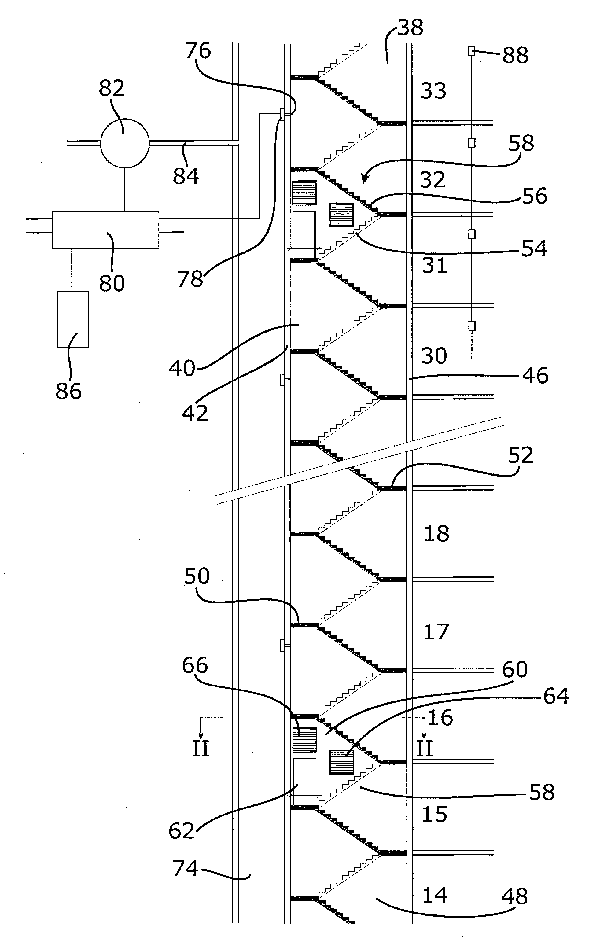
[0040]Of a high-rise building, FIG. 1 shows a stairwell 38 having a vertical shaft. The stairwell 38 extends over the floors 14-33 (with a gap drawn in between 19 and 29). The shaft of the stairwell 38 is limited by walls 40, 42, 44 and 46. The stairwell 38 comprises a staircase 48. The staircase 48 consists of individual floor staircases that are respectively configured, in the example shown, as a U-staircase with a half-landing 50. Each floor staircase includes a landing 52 to which a lower flight of stairs 54 leading into the half-landing 50 adjoins. An upper flight of stairs 56 extends therefrom to the next landing above it of the next floor staircase. A well hole that is normally open is located between the two flights of stairs 54, 56. In the embodiment shown, however, it is closed in the area between the stories 15 and 16 as well as between the stories 31 and 32.

[0041]This is done in each case by means of a partition 58. This partition 58 comprises a partition wall 60. With r...


PUM


Abstract

A high-rise building has a stairwell, an air supply shaft, inlet openings connecting the air supply shaft to the stairwell, and a pressure system for keeping the stairwell free from smoke. The stairwell is vertically divided into several partial spaces. The separation is performed by at least one partition. Each partition has a door enabling a passage from one partial space of the stairwell into an adjacent partial space.

Description

CROSS-REFERENCE TO RELATED APPLICATIONS[0001]This application is a continuation of International Patent Application No. PCT / EP2009 / 063129, filed Oct. 8, 2009 designating the United States, and claims priority under 35 U.S.C. §119(a)-(d) to German Application No. DE 10 2008 050 438.6, filed Oct. 8, 2008, the contents of both of which are hereby incorporated by reference in their entirety as part of the present disclosure.FIELD OF THE INVENTION[0002]The invention relates to a high-rise building with a stairwell, an air supply shaft, inlet openings connecting the air supply shaft to the stairwell, and a pressure system for keeping the stairwell free from smoke, the stairwell is vertically divided into at least two partial spaces by at least one partition, and each partition comprises a door which enables a passage from one partial space of the stairwell into the adjacent partial space.BACKGROUND INFORMATION[0003]In high-rise buildings of up to about 197 ft, i.e., approx. 60 m, that is,...

Claims


Application Information

Patent Timeline
Patent Type & Authority Applications(United States)
IPC IPC(8): E04H14/00F24F7/00F24F13/10A62C2/00
CPCB08B15/00E04H1/04F24F2221/50F24F11/0001F24F2011/0004F24F2011/0095F24F11/33A62B15/00
Inventor ERMER, HORST A.GAIDA, HANS
Owner SWISS RALTEC
Learn More