
Efficient active source impedance modification of a power amplifier

a technology of active source and power amplifier, which is applied in the direction of generator control by field variation, dynamo-electric converter control, electric generator control, etc., can solve the problems of large excursions in the impedance of individual amplifiers, source impedance that is very different from the desired output impedance, system instability, etc., to reduce the power dissipated in the impedance element, reduce the power dissipated by the impedance, and stabilize the effect of interaction

Active Publication Date: 2012-12-11
AES GLOBAL HLDG PTE LTD
View PDF7 Cites 51 Cited by
  • Summary
  • Abstract
  • Description
  • Claims
  • Application Information

AI Technical Summary

Benefits of technology

The present invention is a system and method for stabilizing power that is applied from a generator to a non-linear load. The system includes an impedance element and a power source that work together to reduce power dissipated in the impedance element. This results in a more stable and efficient transfer of power from the generator to the non-linear load. The technical effect of this invention is to improve the stability and efficiency of power transfer between generators and non-linear loads.

Problems solved by technology

Very often sensitivity of a power amplifier's power output to the impedance of a non-linear load (such as a plasma load) connected to the output of the amplifier gives rise to system instabilities.
Many common amplifier technologies, however, such as class D and E amplifiers, have a source impedance that is very different from the desired output impedance.
In addition, the individual amplifiers experience larger excursions in the impedance into which they deliver power than the excursion of the load impedance itself.
This means that when two amplifiers are combined in a balanced amplifier configuration, the power delivery capability into load impedances different from the nominal load impedance (typically 50 ohm) is typically not much better than that of a single amplifier of the same type.
In industrial applications, it is common to accept reflected power equal to 20% of the output capability of an amplifier, which puts strain on the on the design of the hybrid combiner terminating resistor and individual amplifiers and often limits the voltage-current capability of the balanced amplifier.

Method used


Image

  • Efficient active source impedance modification of a power amplifier
  • Efficient active source impedance modification of a power amplifier
  • Efficient active source impedance modification of a power amplifier

Examples


Embodiment Construction

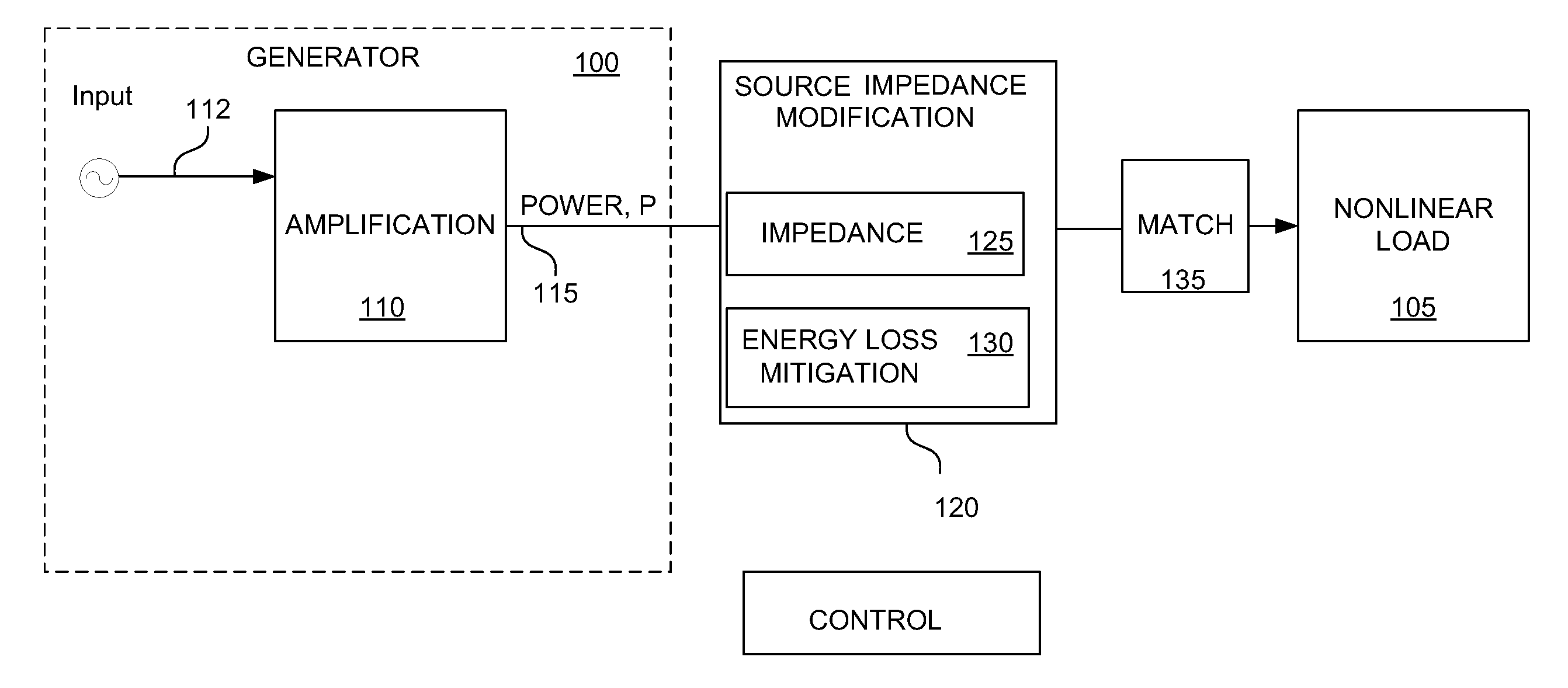
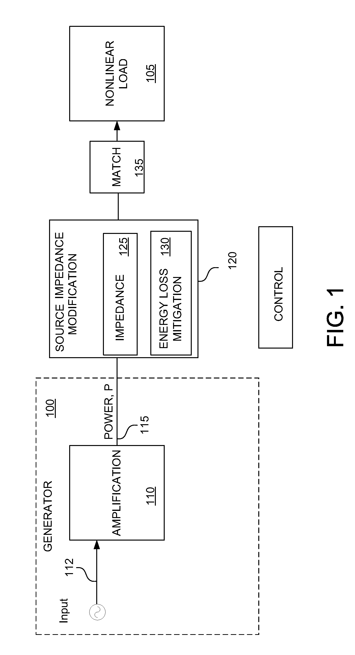
[0017]An understanding of various embodiments of the invention is aided by an analysis of how instability in the output power of an electrical generator can occur as a result of interactions between the generator and the impedance of a nonlinear load with which it is connected. FIG. 1 is a block diagram of a generator 100 connected with a nonlinear load 105 to facilitate such an analysis while depicting an exemplary embodiment of the invention. Generator 100 includes an amplification component 110, which delivers, responsive to a control input 112, output power P 115 to the nonlinear load 105. Nonlinear load 105 in turn presents a load impedance ZL that includes real and imaginary components of which are, respectively, resistance R and reactance X. That is, ZL=RL+jXL.

[0018]In one embodiment, generator 100 is a radio-frequency (RF) generator, and nonlinear load 105 includes a plasma, which can be used in, for example, vapor deposition and etching applications.

[0019]As discussed furth...


PUM


Abstract

A system, method, and apparatus for stabilizing interactions between an electrical generator and a nonlinear load are described. One illustrative embodiment includes an impedance element that is coupled to an output of the generator and a power source coupled to the impedance element. The power source applies power to, or across, the impedance element so as to reduce energy loss that would ordinarily occur due to energy dissipation by way of the impedance element. In many variations, the power source operates within a defined bandwidth so that a stabilizing effect is achieved outside of this bandwidth.

Description

FIELD OF THE INVENTION[0001]The present invention relates generally to electrical generators. In particular, but not by way of limitation, the present invention relates to methods and apparatuses for controlling a source impedance of generators such as are used with plasma processing chambers.BACKGROUND OF THE INVENTION[0002]Very often sensitivity of a power amplifier's power output to the impedance of a non-linear load (such as a plasma load) connected to the output of the amplifier gives rise to system instabilities. A common, but not exclusive, method to control the source impedance of a power amplifier to reduce system instabilities is to use a balanced amplifier configuration, as described by K. Kurokawa, “Design theory of balanced transistor amplifiers”, Bell System Technical Journal, October 1965, to apply power to a load.[0003]If the source impedance of the individual amplifiers used in the balanced amplifier configuration is close to the desired output impedance, no substan...

Claims


Application Information

Patent Timeline
Patent Type & Authority Patents(United States)
IPC IPC(8): H02P9/30
CPCH03F1/56H03H7/40H05H2001/4682H05H2242/26H05H1/46
Inventor VAN ZYL, GIDEONDORRENBACHER, JOHN
Owner AES GLOBAL HLDG PTE LTD
Learn More