
Image forming apparatus and control method of image forming apparatus

a technology of image forming apparatus and control method, which is applied in the direction of digitally marking record carriers, liquid/fluent solid measurements, instruments, etc., can solve the problems of unnecessary power consumption, power saving issues, and inability to achieve further power saving, so as to avoid shortening the lifetime of components and reducing useless power consumption

Active Publication Date: 2012-12-04
CANON KK
View PDF5 Cites 12 Cited by
  • Summary
  • Abstract
  • Description
  • Claims
  • Application Information

AI Technical Summary

Benefits of technology

[0009]The present invention is directed to an image forming apparatus which can reduce useless power consumption and avoid shortening the lifetime of components with an upper limit for a number of activations by preventing the image forming apparatus from unnecessarily recovering from an energy-saving mode.

Problems solved by technology

As a result, further power saving cannot be achieved.
Another power savings issue can arise if user authentication fails.
In the event the user authentication fails, since the image forming apparatus still needed to recover from the energy-saving mode, unnecessary power is consumed until the image forming apparatus shifts back to the energy-saving mode.
In addition, components of the image forming apparatus which have an upper limit for a number of activations will uselessly consume their lifetime because the image forming apparatus unnecessarily recovers from the energy-saving mode.

Method used


Image

  • Image forming apparatus and control method of image forming apparatus
  • Image forming apparatus and control method of image forming apparatus
  • Image forming apparatus and control method of image forming apparatus

Examples

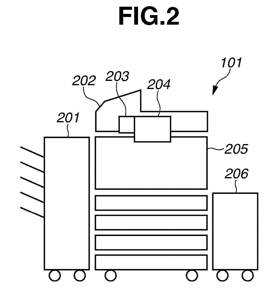

Embodiment Construction

[0030]Various exemplary embodiments, features, and aspects of the invention will be described in detail below with reference to the drawings.

[0031]FIG. 1 illustrates an example of a system configuration including a multifunction peripheral (MFP) which is an example of an image forming apparatus in the present exemplary embodiment.

[0032]An MFP 101 is a multifunction image forming apparatus provided with functions of a copy, a scanner, a FAX, a printer and the like. Client personal computers (PCs) 102 and 103 can send print jobs to the MFP 101, and receive scanned data from the MFP 101. A local area network (LAN) 104 is a network in which the MFP 101, the client PCs 102 and 103 are connected to each other. The LAN 104 uses a system, for instance, Ethernet® or the like, and can send / receive data to / from apparatuses connected to another LAN via the MFP 101, client PCs 102 and 103, and Internet network 105.

[0033]An authentication server 107 is a server for authenticating a user who uses ...


PUM


Abstract

An image forming apparatus includes a power supply unit supplying power to a plurality of components, the power supply unit including a first power mode and a second power mode, the second power mode supplying less power than the first power mode, a control unit controlling which power mode the power supply unit uses, an authentication unit performing a user authentication when power is supplied from the power supply unit in the second power mode and an authentication request received in the second power mode, and a sending unit sending a request signal requesting the control unit to shift the power supply unit to the first power mode when the authentication unit succeeds in the user authentication, wherein the control unit controls the power supply unit to shift from the second power mode to the first power mode upon receipt of the request signal.

Description

BACKGROUND OF THE INVENTION[0001]1. Field of the Invention[0002]The present invention relates to an image forming apparatus which has an energy-saving mode, a normal mode, and a control method thereof.[0003]2. Description of the Related Art[0004]In the conventional image forming apparatus, an authentication is performed by an identification (ID) card which stores a user's identification information, and the user who is correctly authenticated is allowed to use the image forming apparatus. Accordingly, the apparatus can be managed and security is enhanced.[0005]For purposes of saving energy, the image forming apparatus includes an energy-saving mode (also referred to as power-saving mode or sleep mode) for shutting down electric power supply to some parts of the image forming apparatus. When user authentication is performed under the energy-saving mode, the image forming apparatus recovers from the energy-saving mode to the normal mode. (For instance, see Japanese Patent Application ...

Claims


Application Information

Patent Timeline
Patent Type & Authority Patents(United States)
IPC IPC(8): G06K5/00G06F17/00G06F1/00G06K15/22G03G21/00G03G15/00
CPCB41J29/393G03G15/5004G06F21/31G03G15/5091G06F21/81G06F21/34G06F2221/2115
Inventor HASHIMOTO, MINORU
Owner CANON KK
Learn More