
Irradiation sources and methods

a technology of irradiation source and source, which is applied in the direction of x-ray tubes, optical radiation measurement, energy-based chemical/physical/physico-chemical processes, etc., can solve the problems of more radiation to adjacent wall surfaces, more difficult to cure corner materials without, and difficult to cure corner materials, etc., to achieve uniform irradiation of target, improve cooling and ventilation, and improve material irradiation efficiency

Inactive Publication Date: 2012-11-27
GARCIA ANDREW
View PDF13 Cites 11 Cited by
  • Summary
  • Abstract
  • Description
  • Claims
  • Application Information

AI Technical Summary

Benefits of technology

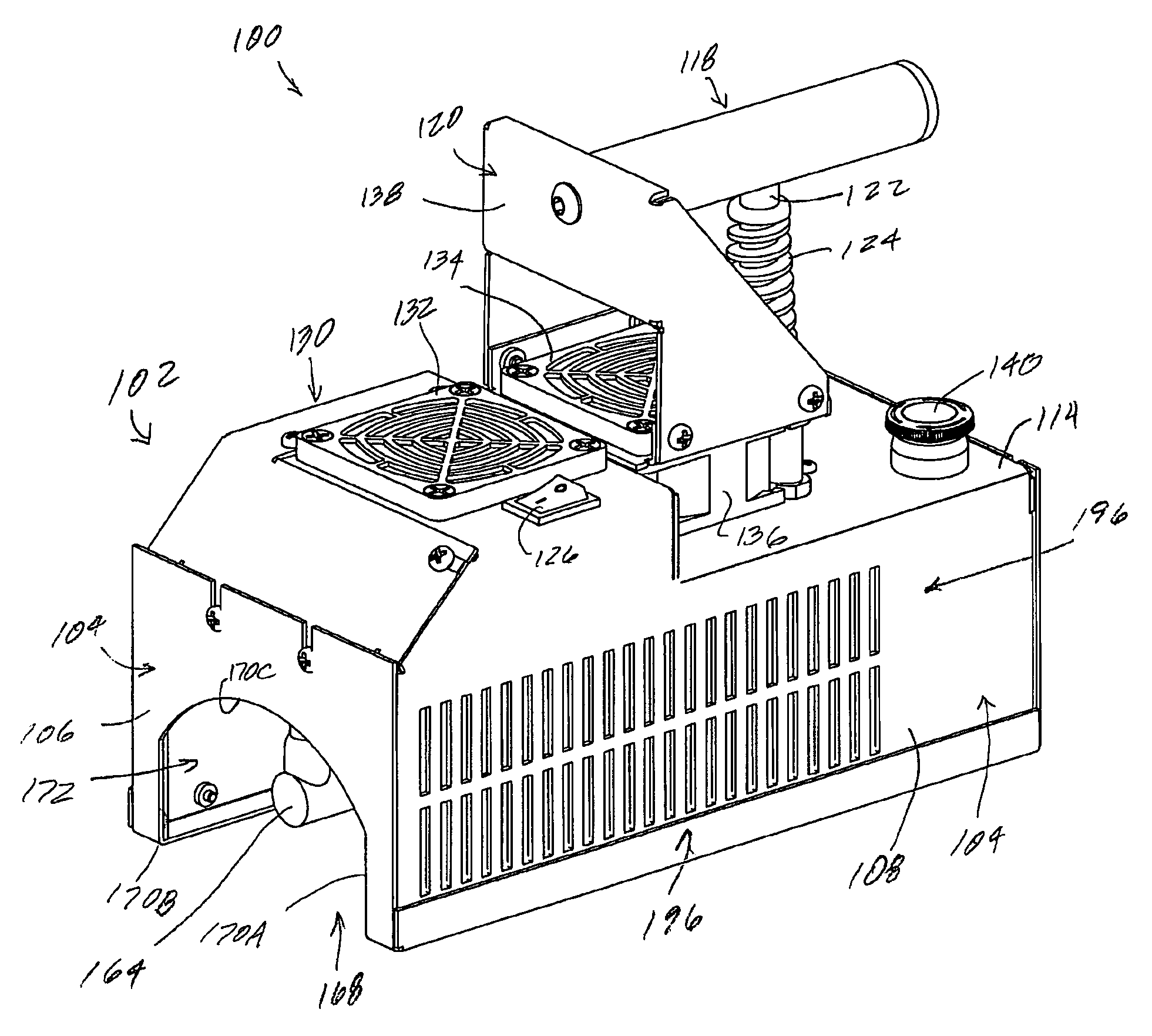
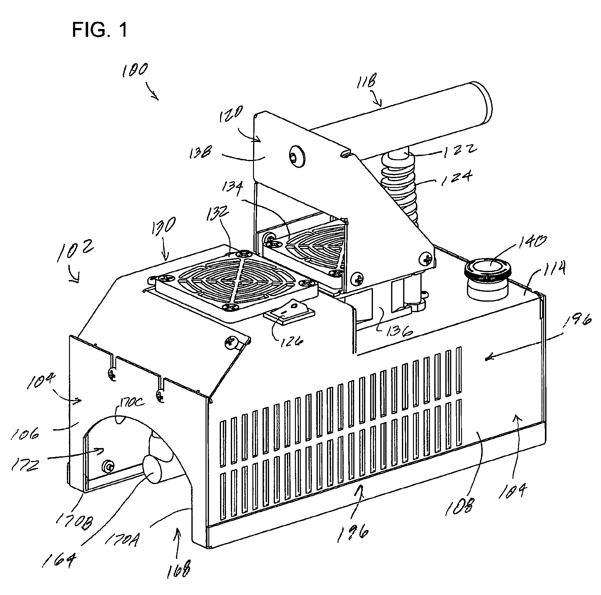
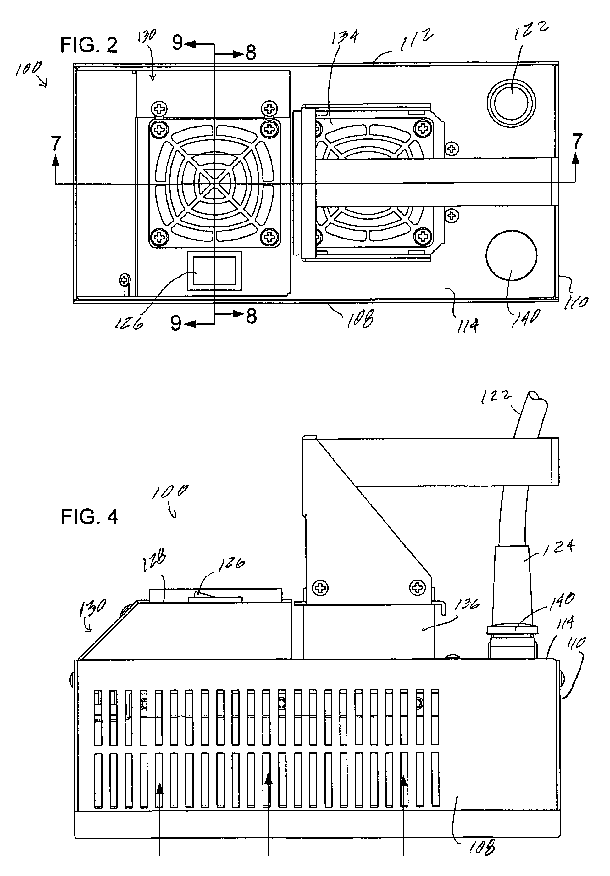
"The patent text describes methods and apparatus for using UV radiation to efficiently irradiate materials, such as coatings, using handheld equipment. The methods and apparatus include a housing with a UV lamp source and a reflector to produce UV radiation. The reflector can be positioned parallel or non-parallel to the UV lamp source, allowing for more versatility and better cooling. The apparatus can also have multiple modes of operation and improved cooling and ventilation. Overall, the methods and apparatus make it easier and more efficient to use UV radiation for curing materials."

Problems solved by technology

Substantially all of the coating on the surface can be cured in this way, but curing surface coatings in a corner of two adjacent walls or in a corner between two walls and a floor or ceiling may be more difficult.
In a corner between two adjacent walls and a floor or a ceiling, it is more difficult to cure the corner material without over-irradiating the adjacent surface material.
As a result, the adjacent wall surfaces may get more radiation than the corner before the corner surfaces are properly cured.
Additionally, equipment design is such that equipment parts such as housing components, reflector parts and the like extend around the sides of the lamp source, making it more difficult to place the lamp source as close to the surface as may be desired for adequate curing.

Method used


Image

  • Irradiation sources and methods
  • Irradiation sources and methods
  • Irradiation sources and methods

Examples


Embodiment Construction

[0035]This specification taken in conjunction with the drawings sets forth examples of apparatus and methods incorporating one or more aspects of the present inventions in such a manner that any person skilled in the art can make and use the inventions. The examples provide the best modes contemplated for carrying out the inventions, although it should be understood that various modifications can be accomplished within the parameters of the present inventions.

[0036]Examples of irradiation sources and of methods of making and using the irradiation sources are described. Depending on what feature or features are incorporated in a given structure or a given method, benefits can be achieved in the structure or the method. For example, irradiation sources with openings facing in different directions may provide more flexibility in use and application. They may also be more efficient during use. Additionally, irradiation sources may be configured to have improved cooling, such as more uni...


PUM


Abstract

Irradiating assemblies can have a housing with a reflector extending linearly parallel to a lamp. Radiation can be emitted from one opening, for example in a bottom portion of the housing, as well as from another opening, for example a side opening in the housing. Irradiating assemblies can also have first and second reflector portions at angles with respect to each other wherein radiation is reflected out of a housing that does not have an end reflector. Irradiating assemblies can be configured to have cooling flow openings in side walls so that cooling fluid such as air can flow between the side walls and adjacent surfaces of a reflector. Irradiating assemblies can incorporate lamps having first and second electrodes wherein the first and second electrodes are oriented at an angle with respect to each other. Methods of irradiating material may include irradiating a surface with emissions from a first portion of an assembly and irradiating a surface with emissions from a second portion of an assembly different from the first portion.

Description

BACKGROUND[0001]1. Field[0002]These inventions relate to irradiation devices and methods, including for example, UV curing apparatus and methods and hand-held UV curing apparatus and methods.[0003]2. Related Art[0004]UV curing apparatus and methods are used for curing photo-initiated adhesives and other coating compositions. UV radiation curing offers significant energy and savings compared to thermal curing in heat ovens. UV radiation curing also is much quicker with significant time savings, and is more environmentally friendly in reducing toxic emissions. Another advantage of UV curing is the adhesives leave behind no solvent residue, as is common with thermoplastic adhesives which set upon cooling or evaporation of a solvent. U.S. Pat. No. 6,000,815, and U.S. published patent publication U.S. 2004 / 0165391, each discuss irradiation lamp assemblies. The descriptions and drawings of those documents are incorporated herein by reference.[0005]In these apparatus, the lamp source is po...

Claims


Application Information

Patent Timeline
Patent Type & Authority Patents(United States)
IPC IPC(8): G21K5/00
CPCB05D3/067B01J19/123H05B3/0057F26B3/28
Inventor GARCIA, ANDREW
Owner GARCIA ANDREW
Learn More