
Vacuum switch tube

a switch tube and vacuum technology, applied in the direction of air-break switches, high-tension/heavy-dress switches, electrical apparatus, etc., can solve the problems of forming a desirable vertical magnetic field, reducing the current breaking capability of contacts, and extremely intense arc generated between switch contacts, etc., to reduce re-ignition possibility, effective arc-extinguishing, and reduce arc voltage

Active Publication Date: 2012-11-27
BEIJING ORIENT VACUUM ELECTRIC
View PDF6 Cites 1 Cited by
  • Summary
  • Abstract
  • Description
  • Claims
  • Application Information

AI Technical Summary

Benefits of technology

[0006]The present invention is directed to a vacuum switch tube, which is applicable to reduce re-ignition possibility during voltage breaking, decrease an arc voltage, realize effective arc-extinguishing, and satisfy high voltage breaking requirements.
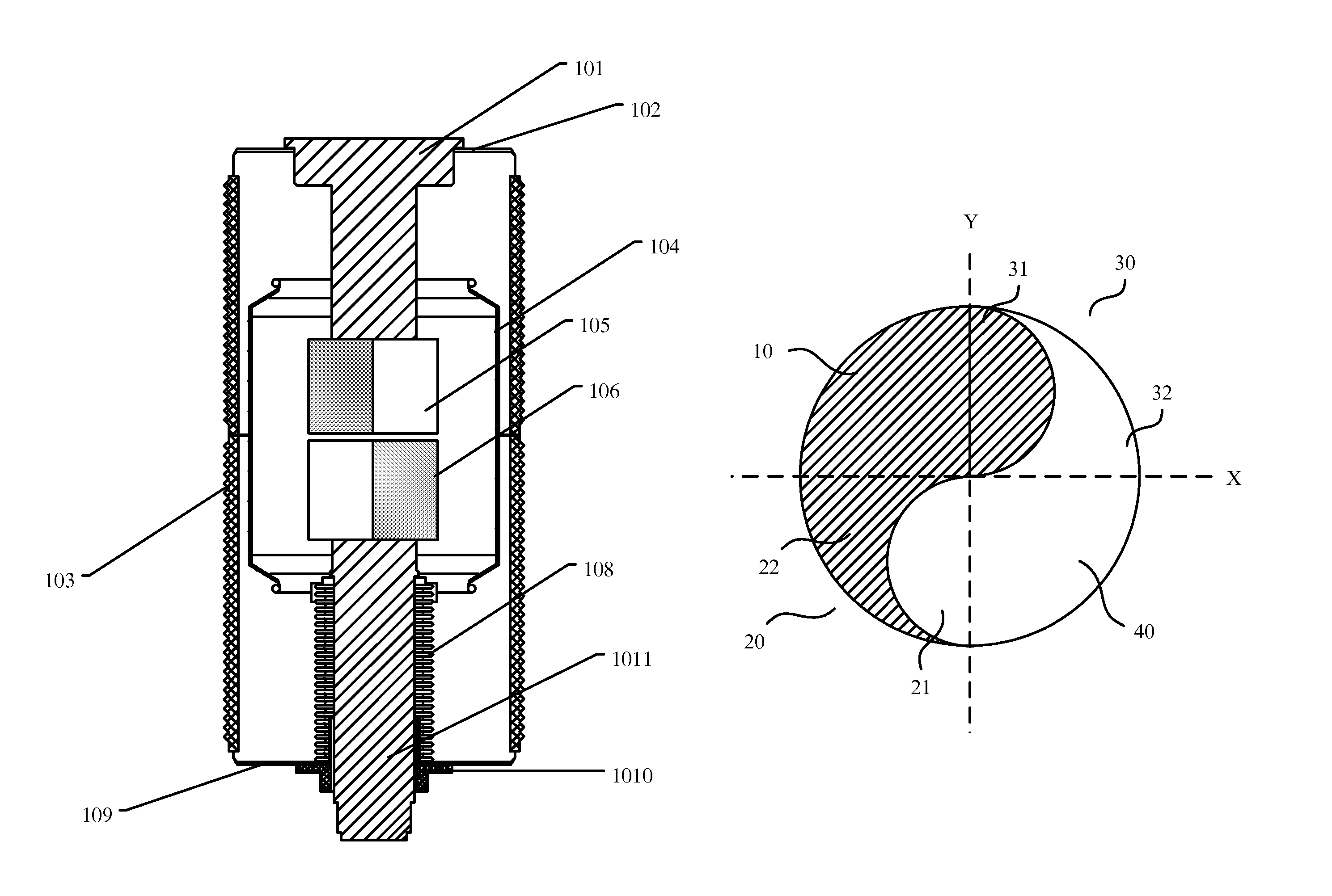
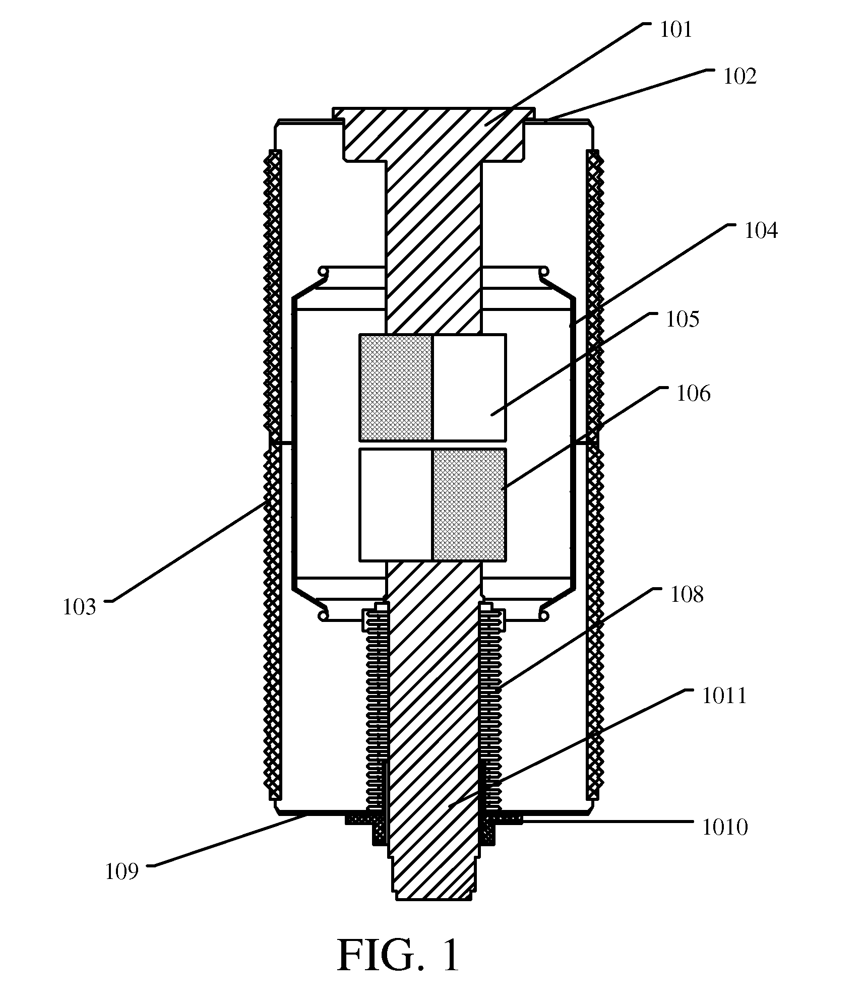
[0014]The present invention provides a vacuum switch tube, in which the conductive members and the magnetic members form the contact bodies of the two contacts, and the shape of the magnetic members is unequal. Therefore, an uneven magnetic field is formed, in which one end of the magnetic field has a high intensity and the other end has a low intensity. In addition, since the magnetic members of the two vacuum switch contacts are anti-symmetrically disposed, when a magnetic field generated by the magnetic member of one vacuum switch contact and a magnetic field generated by the magnetic member of the other vacuum switch contact form a magnetic field loop, a rotating magnetic field having both a horizontal magnetic field and a vertical magnetic field and rotating lines of magnetic force is generated between the two vacuum switch contacts, so that the re-ignition possibility during voltage breaking is effectively reduced, the arc voltage is decreased, and the effective arc-extinguishing is realized, thereby satisfying the high voltage breaking requirements.

Problems solved by technology

Especially in a high voltage circuit, the arc generated between the switch contacts is extremely intense.
The arc raises the temperature of the switch, which wears the switch, and the current breaking capability of contacts is decreased because the arc occurs.
However, in the current vacuum switch contacts, due to the restriction of structural shapes, it is usually very difficult to form a desirable vertical magnetic field for performing arc-extinguishing, and it is rather difficult to solve problems such as electric field concentration, insufficient voltage resistance, and high re-ignition possibility during the high voltage breaking process.
For a higher voltage circuit, particularly, 72-kilovolt high voltage circuit, currently, no vacuum switch tube structure is available for satisfying effective arc-extinguishing requirements during the breaking process.
This is one of the problems to be solved in the vacuum switch technology in the prior art.

Method used


Image

  • Vacuum switch tube
  • Vacuum switch tube
  • Vacuum switch tube

Examples


first embodiment

[0022 of Vacuum Switch Tube

[0023]FIG. 1 is a schematic structural view of a vacuum switch tube according to a first embodiment of the present invention. As shown in FIG. 1, the vacuum switch tube includes an insulating housing 103, that is, a vacuum tube body. An upper end cover 102 and a lower end cover 109 are disposed at an upper end and a lower end of the insulating housing 103 respectively. Two conductive rods are disposed inside the insulating housing 103, which are a first conductive rod 1011 and a second conductive rod 101 respectively. A first contact 106 is disposed at an end of the first conductive rod 1011. The first conductive rod 1011 movably penetrates a through hole of the lower end cover 109 through a guide sleeve 1010. The guide sleeve 1010 is fixedly disposed in the through hole of the lower end cover 109. A through hole is opened in the guide sleeve 1010, so that the first conductive rod 1011 is enabled to movably penetrate there through. A sylphon bellowss 108 i...

second embodiment

[0032 of Vacuum Switch Tube

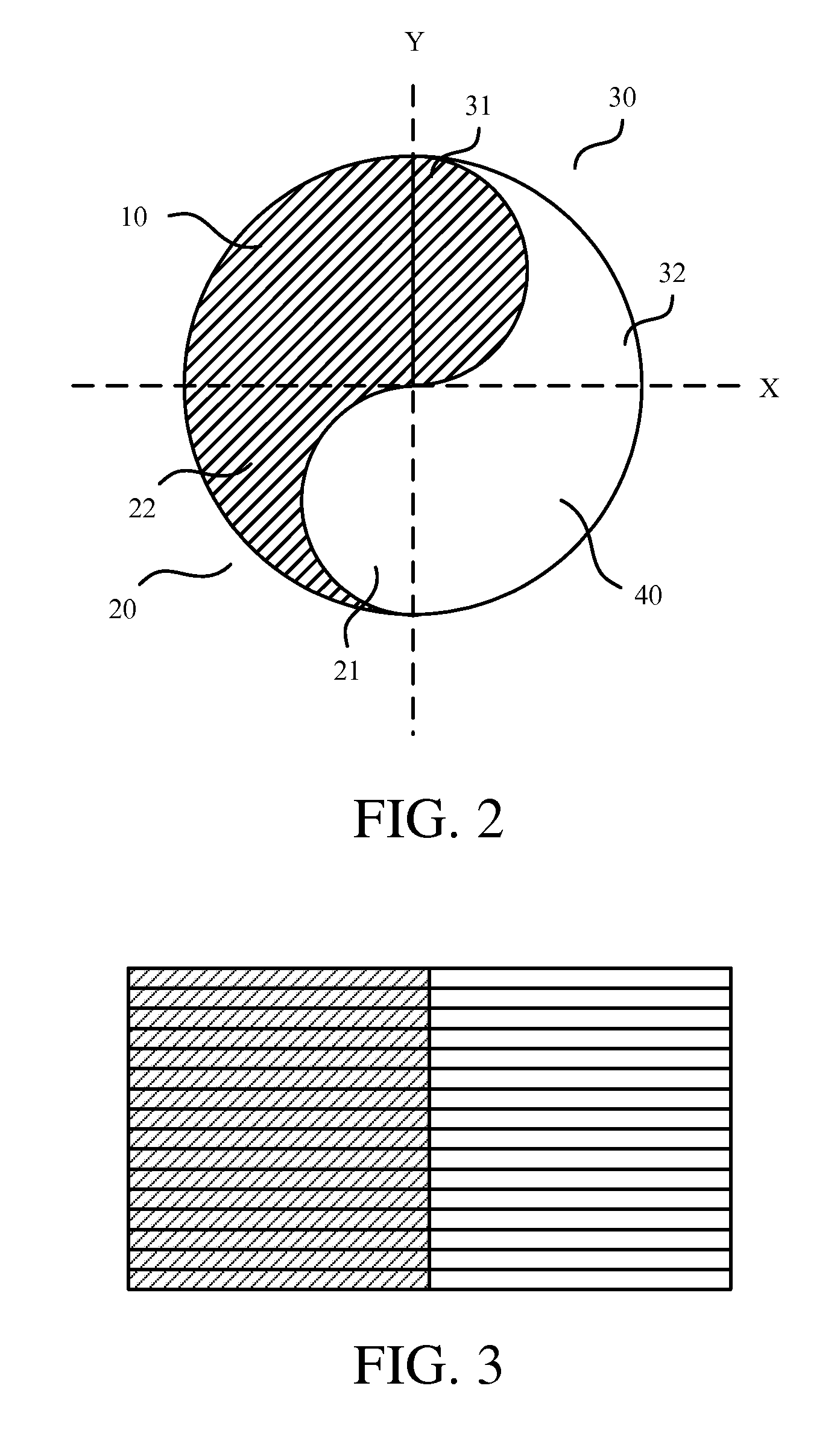
[0033]FIG. 3 is a schematic structural side view of a contact body of a vacuum switch tube according to a second embodiment of the present invention. In this embodiment, contact bodies of the first contact and the second contact are both formed by a plurality of sheets laminated in sequence. Taking the first contact as an example, each of the sheets is formed by a conductive sheet and a magnetic sheet joining and combining with each other. A plurality of conductive sheets forms the conductive member. A plurality of magnetic sheets forms the magnetic member. The shapes of cross sections of the conductive sheets and the magnetic sheets and a structural relation between the conductive member and the magnetic member may adopt the technical solution in the above embodiment, in which the shapes of the cross sections of the conductive sheets and the magnetic sheets are yin-yang-fish matched. All the sheets are laminated together to form a shape of an external pro...

third embodiment

[0034 of Vacuum Switch Tube

[0035]FIG. 4 is schematic structural view of a cross section of a contact body of a vacuum switch tube according to a third embodiment of the present invention. On the basis of the second embodiment, in order to secure relative positions of the conductive member and the magnetic member before the sheets are melted and solidified, securing holes 200 penetrating the plurality of sheets may be further opened in the conductive sheets 300 and the magnetic sheets 400. Securing columns 100 are inserted in the securing holes 200, as shown in FIG. 4, and one end of each of the securing columns 100 is secured at a bottom portion inside the metal shell 500. The securing columns 100 may be made of the same material as the conductive member, for example, copper.

[0036]The contact bodies are not limited to consist of sheets, and the contact bodies also may be consist of a plurality of conductive and magnetic poles or particles adjacent each other closely.

[0037]The techni...


PUM


Abstract

The present invention relates to a vacuum switch tube, which includes a first contact and a second contact disposed on conductive rods respectively. The two contacts are disposed facing each other. The two contacts are cylinders and include conductive members and magnetic members to form contact bodies. The cross section shape of the magnetic members is divided by a neutrality line into two unequal regions. The magnetic member of the first contact and the conductive member of the second contact are disposed corresponding to each other. The conductive member of the first contact and the magnetic member of the second contact are disposed corresponding to each other. The two vacuum switch contacts are anti-symmetrically disposed, such that a rotating magnetic field having rotating lines of magnetic force is formed, so that re-ignition possibility during voltage breaking is effectively reduced, and an arc voltage is decreased.

Description

FIELD OF THE TECHNOLOGY[0001]The present invention relates to a vacuum switch tube, and more particularly to a vacuum switch tube with corresponding contacts disposed in an arc-extinguishing chamber, which belongs to the field of electric technology.BACKGROUND[0002]A switch device is an essential device in a circuit, which functions to turn on and off the circuit. When the two contacts in a switch device are disconnected, an arc is generated, e.g., a plasma arc column with a conical surface is generated from the combustion at the cathode spot. Especially in a high voltage circuit, the arc generated between the switch contacts is extremely intense.[0003]The arc raises the temperature of the switch, which wears the switch, and the current breaking capability of contacts is decreased because the arc occurs. Therefore, when the switch contacts are turned on and off, the arc-extinguishing process must be performed. In the switch device in the prior art, an arc-extinguishing medium such a...

Claims


Application Information

Patent Timeline
Patent Type & Authority Patents(United States)
IPC IPC(8): H01H33/66
CPCH01H33/66H01H33/664
Inventor REN, JIANCHANG
Owner BEIJING ORIENT VACUUM ELECTRIC
Learn More