Device for machining a workpiece by means of parallel laser beams

a technology of laser beams and workpieces, applied in laser beam welding apparatus, welding apparatus, metal-working apparatus, etc., can solve the problems of difficult adjustment of the spacing between laser beams, more particularly step-free, and desired results, and achieve the effect of reducing design complexity

Inactive Publication Date: 2012-11-20
LPKF LASER & ELECTRONICS
View PDF10 Cites 0 Cited by
  • Summary
  • Abstract
  • Description
  • Claims
  • Application Information

AI Technical Summary

Benefits of technology

[0009]An aspect of the present invention provides a simple option for changing the spacing between the laser beams and, in the process, avoiding a change in the focusing plane as a result of the change in the spacing between the parallel laser beams and so the control complexity can be kept to a minimum. More particularly, it should be possible for a change in the spacing to be realized using a single drive.
[0010]Thus, according to the invention, provision is made for a device in which four laser beams form at least two laser beam pairs and each laser beam pair is formed by two laser beams equidistant from an axis of symmetry, wherein each laser beam can be deflected on reflection surfaces of at least two reflectors that, together with the focusing optical system, can be displaced, in particular translated, relative to one another in the direction of the axis of symmetry in order to adjust the relative spacing between the adjacent laser beams in the focusing plane, wherein the number of reflections of the laser beams of the first laser beam pair corresponds to three times the number of reflections of the laser beams of the second laser beam pair on the displaceable reflector. What is surprisingly achieved by this for the first time is a step-free adjustment of the relative mutual spacing between the adjacent laser beams with an axis of symmetry remaining unchanged. Here, the first laser beam pair is formed by the outer laser beams with respect to the focusing plane and the second laser beam pair is formed by the inner laser beams with respect to the focusing plane. Due to the multiple reflections of the outer laser beam pair, the change in spacing between the outer laser beams and the axis of symmetry for adjusting the changed relative spacing between the laser beams amongst themselves is three times larger than the change in spacing between the inner laser beams and the axis of symmetry. This makes it possible both to keep a fixed axis of symmetry and ensure a matching spacing between all laser beams amongst themselves. For this, the reflectors are moved relative to one another in the direction of the axis of symmetry by at least the reflection surfaces of one reflector being built on a common platform that can be moved by electromotor. Of course, the reflection surfaces can be designed such that they can be adjusted independently of one another. Furthermore, the various reflection surfaces of a reflector could be combined in a functional unit forming the reflector as separate components or else they could be interconnected in an assembly.
[0011]A particularly advantageous embodiment of the present invention is also achieved by virtue of the fact that the displaceable reflection surfaces are designed such that each laser beam of the first laser beam pair is reflected precisely three times and each laser beam of the second laser beam pair is reflected precisely once on the reflection surfaces of the two reflectors. The multiple reflections of the laser beams achieve a threefold increase in the shift perpendicular to the axis of symmetry in a surprisingly simple fashion, and this displacement corresponds to the required value of the shift for maintaining corresponding spacings between all laser beams.

Problems solved by technology

In practice, the desired, more particularly step-free, adjustability of the spacing between the laser beams was found to be problematic.
A disadvantage of this proposed solution was found to be that the change of the spacing was simultaneously connected to the change in the central position of the two laser beams, the latter change having to be compensated for by a superimposed displacement of the entire device.

Method used


Image

  • Device for machining a workpiece by means of parallel laser beams
  • Device for machining a workpiece by means of parallel laser beams
  • Device for machining a workpiece by means of parallel laser beams

Examples


Embodiment Construction

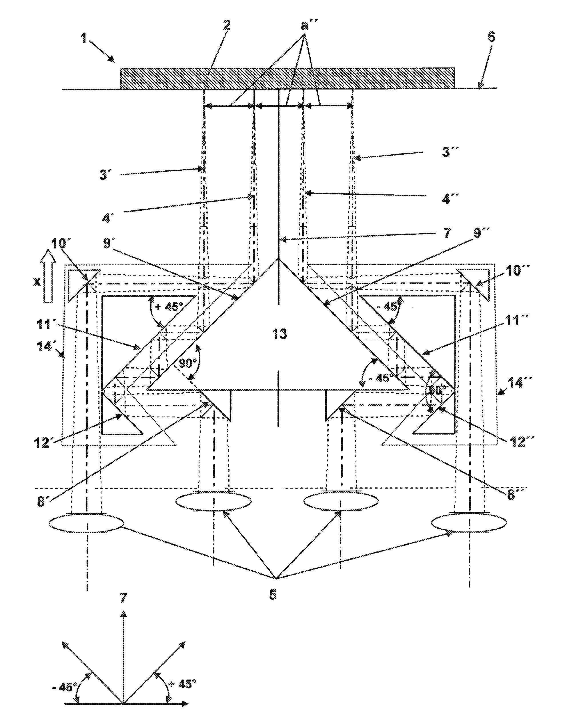
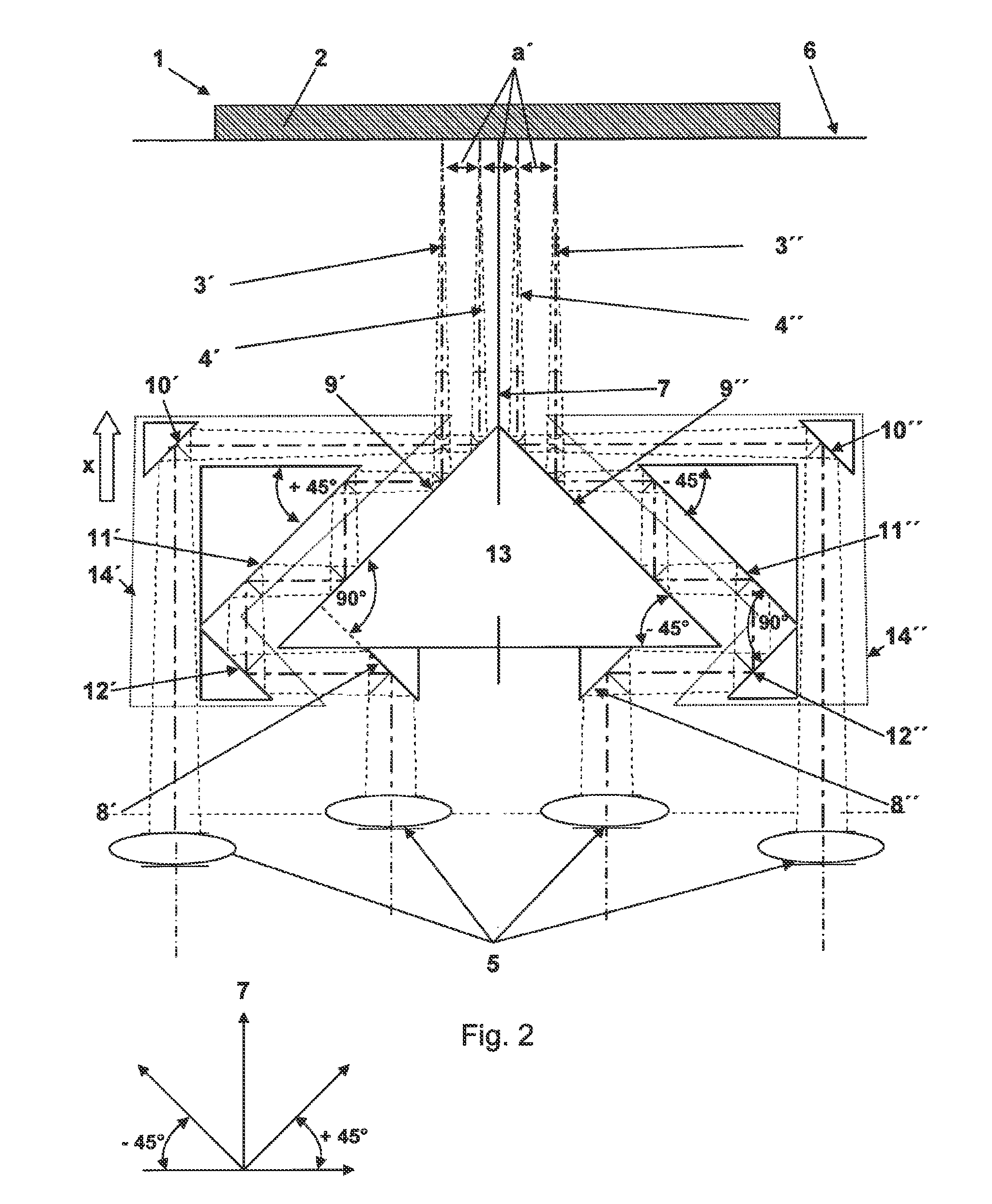
[0024]FIGS. 1 and 2 are used to illustrate the device 1 according to the invention for processing a workpiece 2 in more detail in two functional positions, in which the parallel laser beams 3′, 3″, 4′, 4″ have firstly a large spacing a′, a″ (FIG. 1) and secondly a small spacing a′, a″ (FIG. 2) between one another. The device 1 has a plurality of focusing optical systems 5 assigned in each case to a laser beam 3′, 3″, 4′, 4″ for focusing each laser beam 3′, 3″, 4′, 4″ on a common focusing plane 6 on the workpiece 2. The laser beams 3′, 3″, 4′, 4″ form an outer first laser beam pair 3 and an inner second laser beam pair 4. The laser beams 3′, 3″, 4′, 4″ of each laser beam pair 3, 4 are equidistant from an axis of symmetry 7, independent of the spacing a′, a″ set in each case. Before the laser beams 3′, 3″, 4′, 4″ emanating from the respective focusing optical system 5 impinge on the workpiece 2, each laser beam 3′, 3″, 4′, 4″ is deflected on the reflection surfaces 8′, 8″, 9′, 9″, 10′...


PUM

PropertyMeasurementUnit
angleaaaaaaaaaa
angleaaaaaaaaaa
angleaaaaaaaaaa

Abstract

A device for processing a workpiece using a plurality of parallel laser beams includes a focusing optical system displaceable in a direction of an axis of symmetry configured to focus each of the plurality of parallel laser beams onto a common focusing plane, and wherein the plurality of laser beams include a first and a second laser beam pair, each containing two laser beams equidistant from the axis of symmetry. The device further includes a reflector assembly having at least two reflectors each having a plurality of reflection surfaces displaceable relative to one another in a direction of the axis of symmetry.

Description

[0001]This application is a U.S. National Phase application under 35 U.S.C. §371 of International Application No. PCT / DE2008 / 001762, filed Oct. 31, 2008 and claims benefit to German Patent Application No. DE 10 2007 056 254.5, filed Nov. 21, 2007. The International Application was published in German on May 28, 2009 as WO 2009 / 065373 under PCT Article 21 (2).[0002]The invention relates to a device for processing a workpiece by means of a plurality of at least approximately parallel laser beams, wherein the device is equipped with at least one focusing optical system for focusing each laser beam onto a common focusing plane.BACKGROUND[0003]In practice, such a device serves for simultaneous, for example parallel, processing of the workpiece by means of the parallel laser beams. In the case of a simple design, a semitransparent mirror is used as a beam splitter, which is followed in the beam path of at least one laser beam by a reflector in order to thereby generate a parallel beam pat...

Claims


Application Information

Patent Timeline
Patent Type & Authority Patents(United States)
IPC IPC(8): B23K26/00
CPCB23K26/067B23K26/0676
Inventor KUESTER, MATTHIASKRIEG, CHRISTIANKUSNEZOW, GENNADIJHUESKE, MARC
Owner LPKF LASER & ELECTRONICS
Why Eureka
Try Eureka