
Combustor nozzle and method for supplying fuel to a combustor

a combustor and nozzle technology, applied in the direction of combustion types, burner control devices, turbine/propulsion engine ignition, etc., can solve the problems of increased maintenance, reduced operating limits, severe damage to the nozzle, etc., and achieve the effect of increasing the mass flow rate of the working fluid

Inactive Publication Date: 2012-11-13
GENERAL ELECTRIC CO
View PDF6 Cites 9 Cited by
  • Summary
  • Abstract
  • Description
  • Claims
  • Application Information

AI Technical Summary

Benefits of technology

"The present invention is related to a combustor nozzle and a method for supplying fuel to a combustor. The technical effects of the invention include a center body and a shroud that can pivot with respect to the center body, a guide that can pivot with respect to the center body, and a method for sensing a flame holding event and increasing the mass flow rate of the working fluid flowing through the nozzle. These features and advantages can improve the performance and efficiency of combustion systems."

Problems solved by technology

Nozzles are typically not designed to withstand the high temperatures created by a flame holding event, and flame holding may therefore cause severe damage to a nozzle in a relatively short amount of time.
While the safety margins are effective at preventing or reducing the occurrence of flame holding, they may also result in reduced operating limits, additional maintenance, reduced operating lifetimes, and / or reduced overall thermodynamic efficiency.

Method used


Image

  • Combustor nozzle and method for supplying fuel to a combustor
  • Combustor nozzle and method for supplying fuel to a combustor
  • Combustor nozzle and method for supplying fuel to a combustor

Examples


Embodiment Construction

[0023]Reference will now be made in detail to present embodiments of the invention, one or more examples of which are illustrated in the accompanying drawings. The detailed description uses numerical and letter designations to refer to features in the drawings. Like or similar designations in the drawings and description have been used to refer to like or similar parts of the invention.

[0024]Each example is provided by way of explanation of the invention, not limitation of the invention. In fact, it will be apparent to those skilled in the art that modifications and variations can be made in the present invention without departing from the scope or spirit thereof. For instance, features illustrated or described as part of one embodiment may be used on another embodiment to yield a still further embodiment. Thus, it is intended that the present invention covers such modifications and variations as come within the scope of the appended claims and their equivalents.

[0025]Various embodi...


PUM


Abstract

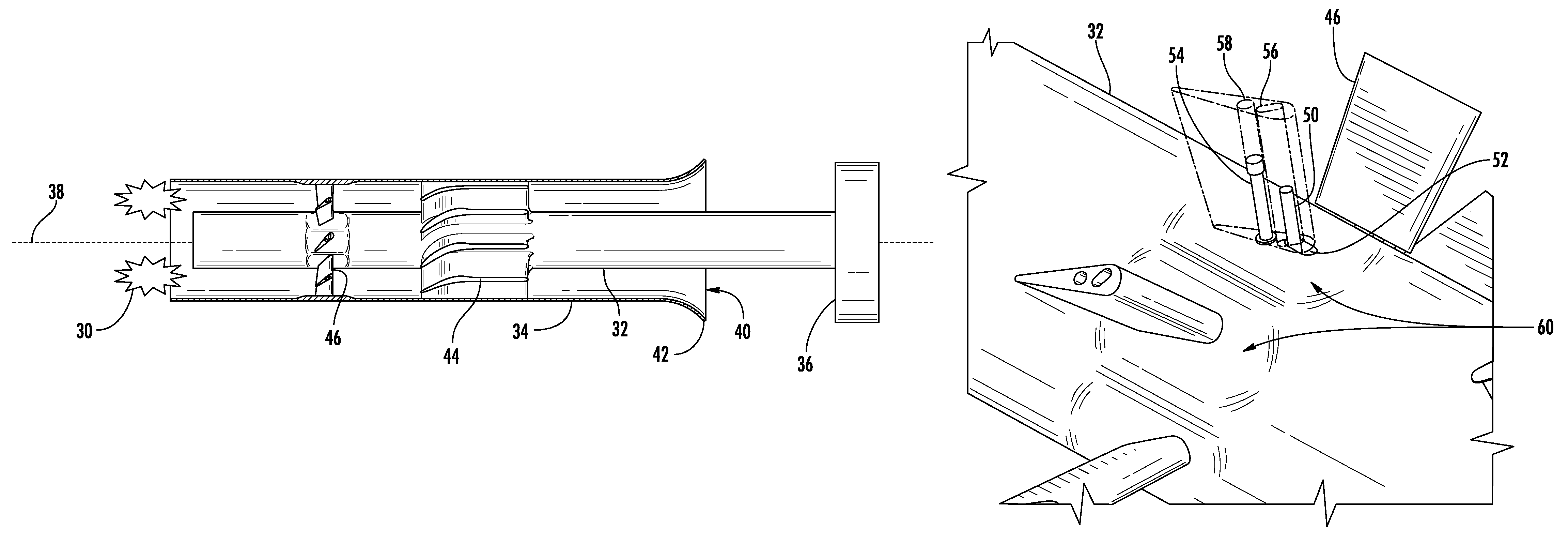
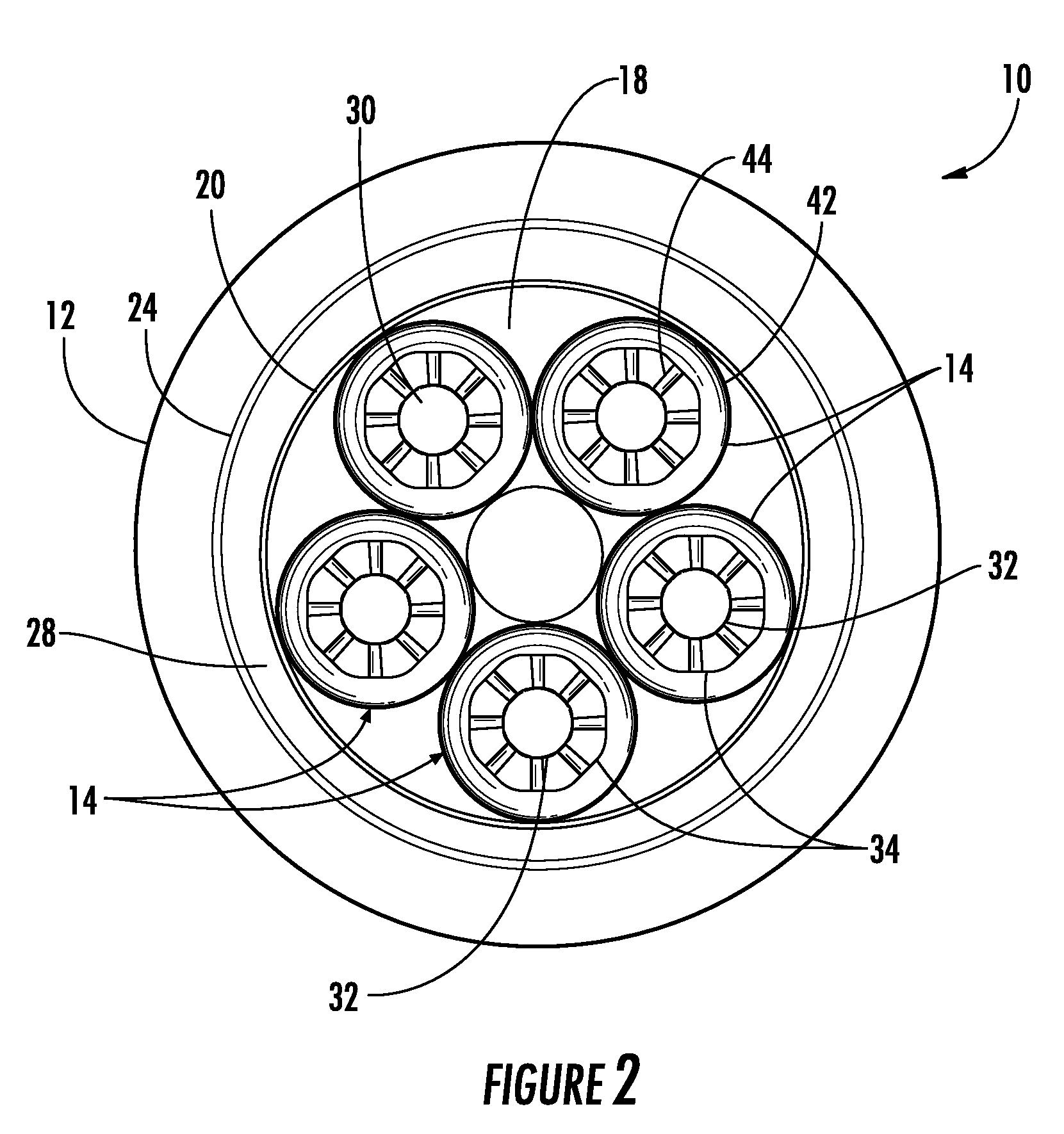
A combustor nozzle includes a center body and a shroud circumferentially surrounding at least a portion of the center body to define a passage between the center body and the shroud. A guide between the center body and the shroud can pivot with respect to the center body. A method for supplying fuel to a combustor includes flowing a working fluid through a nozzle at a mass flow rate and flowing a fuel through the nozzle. The method further includes sensing a flame holding event inside the nozzle and pivoting a guide inside the nozzle to increase the mass flow rate of the working fluid flowing through the nozzle.

Description

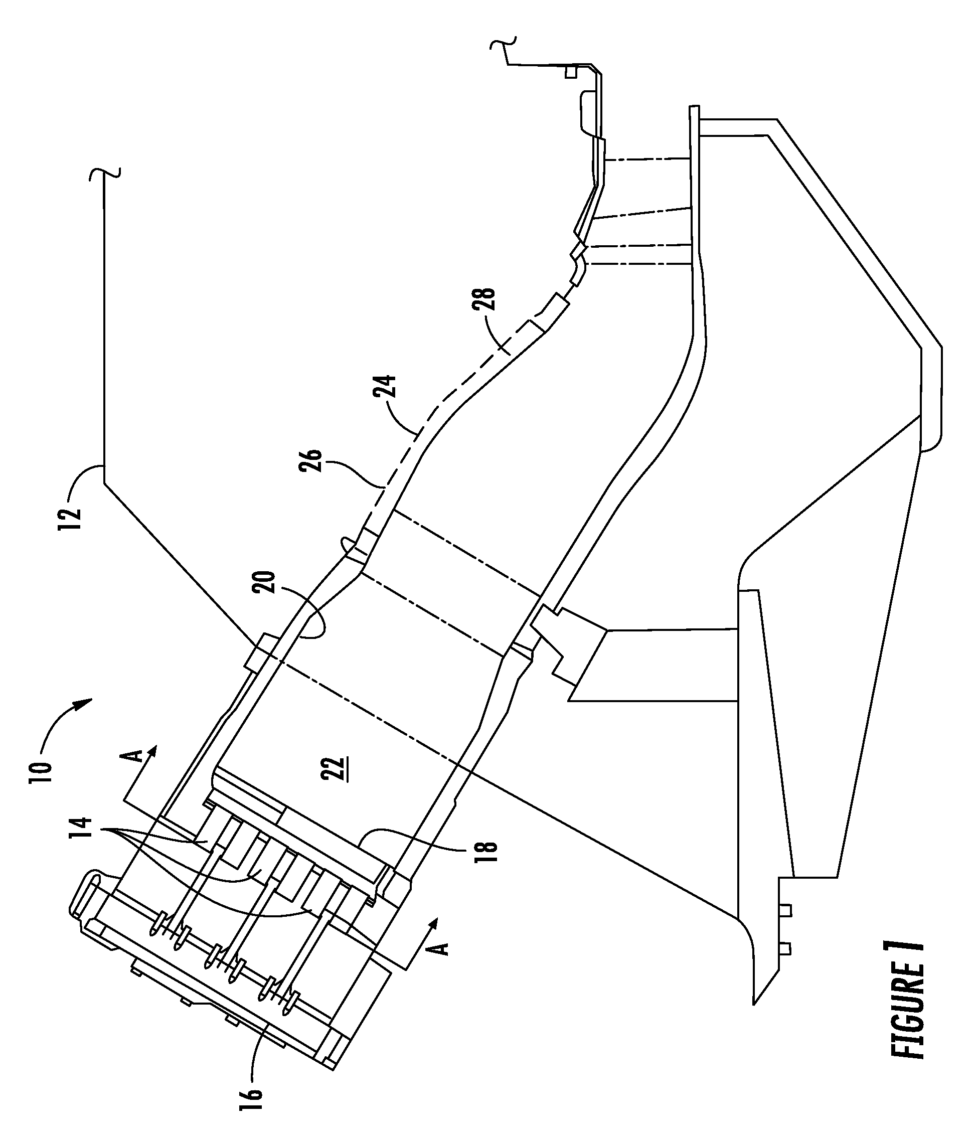
FIELD OF THE INVENTION[0001]The present invention generally involves a combustor nozzle. In particular, the present invention describes and enables a nozzle for a combustor and a method for responding to a flame holding event in the combustor nozzle.BACKGROUND OF THE INVENTION[0002]Combustors are commonly used in many forms of commercial equipment. For example, gas turbines typically include one or more combustors that mix fuel with a working fluid to generate combustion gases having a high temperature and pressure. Many combustors include nozzles that premix the fuel with the working fluid prior to combustion. Premixing the fuel with the working fluid prior to combustion allows for leaner fuel mixtures, reduces undesirable emissions, and / or improves the overall thermodynamic efficiency of the gas turbine.[0003]During normal combustor operations, a combustion flame exists downstream from the nozzles, typically in a combustion chamber at the exit of the nozzles. Occasionally, however...

Claims


Application Information

Patent Timeline
Patent Type & Authority Patents(United States)
IPC IPC(8): F02C1/00
CPCF23C7/006F23D14/70F23R3/14F23R3/286F23D2208/10F23D2209/20F23D2900/00003F23D2900/11402
Inventor STEWART, JASON THURMANJOHNSON, THOMAS EDWARD
Owner GENERAL ELECTRIC CO
Learn More