
Firing device

a technology of projectiles and firing devices, which is applied in the direction of ammunition fuzes, weapons, ammunition projectiles, etc., can solve the problems that the functional reliability of the firing system cannot always be guaranteed, and the sensitive components of the firing device are negatively affected or even destroyed, so as to achieve high cost-effective effects

Active Publication Date: 2012-10-30
RHEINMETALL WAFFE MUNITION GMBH
View PDF24 Cites 4 Cited by
  • Summary
  • Abstract
  • Description
  • Claims
  • Application Information

AI Technical Summary

Benefits of technology

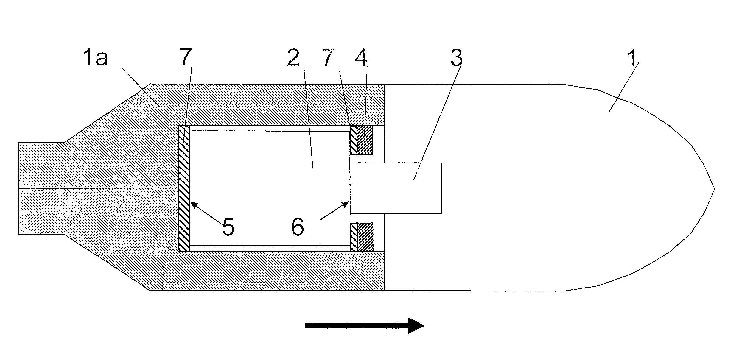
[0011]In contrast, the present invention employs a solution that provides damping and mechanical decoupling of the firing device, which is included in a fixed manner in the projectile, as a result of which peaks on impact are dissipated and can no longer have a destructive effect on the mechanical and electronic components. The additionally included damping device therefore reduces the effects of the projectile oscillations by means of additional materials of low density and with high damping characteristics with respect to both sound waves and shock waves. The damping device, in according to the present invention, decouples the firing device from the mostly metallic structural area in the projectile.
[0015]The thickness of the discs is, in accordance with the present invention, matched to the load spectra (for example, by simulation), thus allowing optimization of the damping system, in particular, for specific targets.
[0017]Virtually complete packaging of the fuze with the material that absorbs the damping is also possible and technically feasible, in accordance with the present invention.

Problems solved by technology

In projectiles having a firing device, whose fuze is intended to still be functional during or after the penetration of targets, the problem arises that the oscillations of the projectile initiated by the impact shock can have a negative influence on, or even destroy, the sensitive components of the firing device.
However, in the case of extreme target structures, measures such as these are not sufficient, and the functional reliability of the firing system cannot always be guaranteed, since they are not sufficient to compensate for the oscillations (for example, on building targets), which occur in or on the fuze on penetration.

Method used


Image

  • Firing device
  • Firing device

Examples


Embodiment Construction

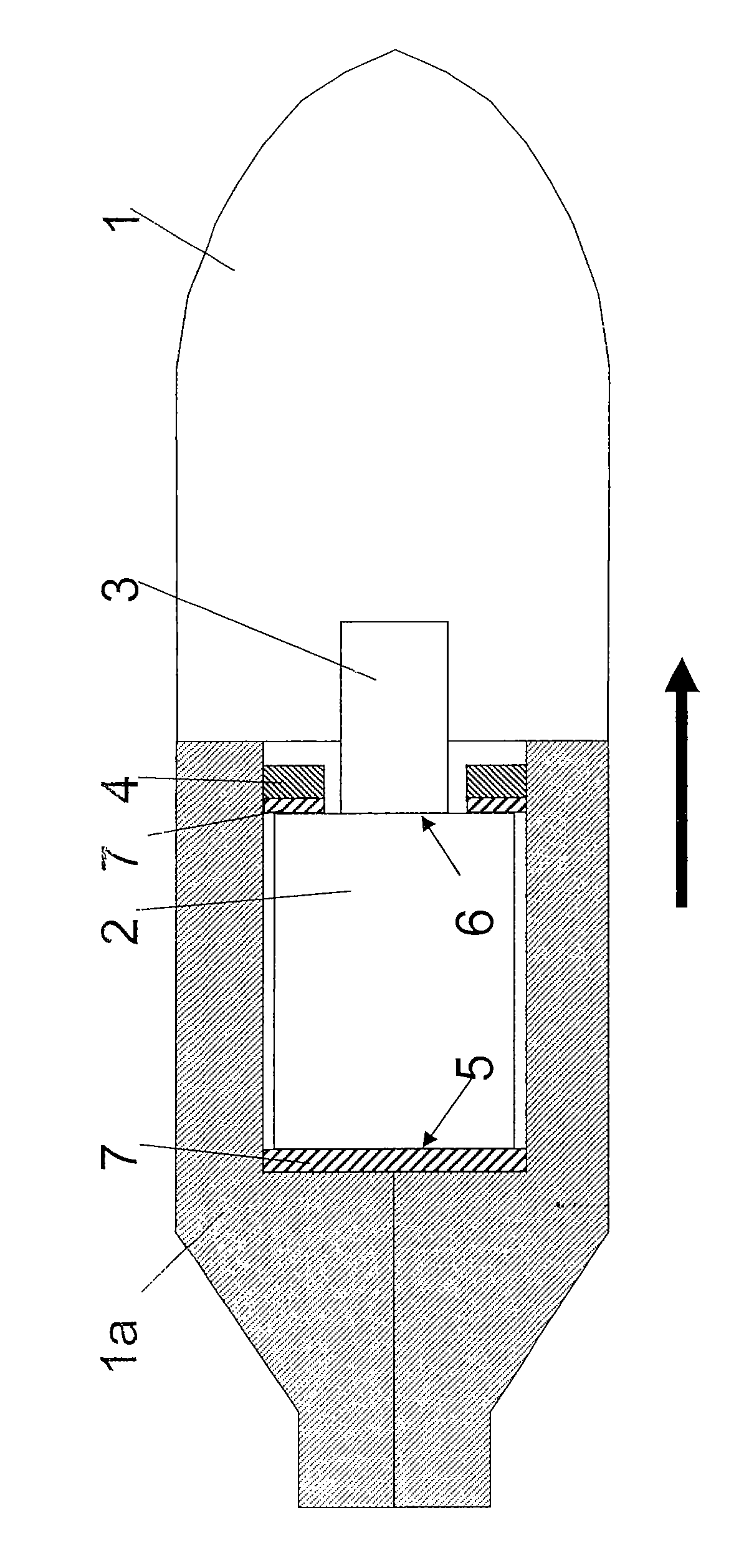
[0019]In the drawing, the single FIGURE shows a projectile 1 with a rear part 1a in which a firing system is located comprising a fuze 2 and a firing booster 3 (if provided in the embodiment design). The firing system is held in the projectile 1 by, for example, a threaded ring 4 or an attachment element of some similar type.

[0020]At least one damping element 7 is inserted between a fuze base 5 and the projectile 1 and / or between a fuze shoulder 6 and the threaded ring 4. The damping element 7, which is in the form of a disc or ring (or else is U-shaped), is preferably composed of plastic (for example, polyethylene=PE) or of a material with a lower acoustic impedance than the material of the projectile 1. The threaded ring 4 is preferably tightened with a defined torque. In consequence, the damping surfaces of the material of the damping element 7 rest completely on the firing system and no gaps are created. At the same time, it is used to fix the firing system and for its attachmen...


PUM


Abstract

The invention relates to so-called fuze damping in projectiles, in particular, those provided with a built-in firing delay. Thus, a projectile (1) is provided having a rear part (1a) and a fuze (2), wherein at least one damping element (7) is inserted between a fuze base (5) and the projectile (1) and / or between a fuze shoulder (6) and a possible threaded ring (4), or similar attachment element. The damping element (7) is in the form of a disc, ring or pot, and is composed of a material with a lower acoustic impedance than the material of the projectile (1).

Description

[0001]This application claims priority from German Patent Application No. 10 2008 057 769.3, filed Nov. 17, 2008, the entire disclosure of which is incorporated herein by reference.FIELD OF THE INVENTION[0002]The invention relates to a so-called fuze damping in projectiles, in particular with a built-in firing delay.BACKGROUND OF THE INVENTION[0003]In projectiles having a firing device, whose fuze is intended to still be functional during or after the penetration of targets, the problem arises that the oscillations of the projectile initiated by the impact shock can have a negative influence on, or even destroy, the sensitive components of the firing device. The oscillations, which are transmitted to the firing device, are caused on the one hand by the sudden deceleration of the projectile and on the other hand by shock waves or sound waves that are introduced into the projectile.[0004]In previous practice, the fuze components were therefore hardened and / or encapsulated in order, in...

Claims


Application Information

Patent Timeline
Patent Type & Authority Patents(United States)
IPC IPC(8): F42B99/00
CPCF42C19/02F42B12/207
Inventor HOFFMANN, WOLFGANGSCHERGE, WOLFGANGLENGNICK, MATHIASBRASE, HOLGERKELL, STEFANNIEMEYER, TORSTEN
Owner RHEINMETALL WAFFE MUNITION GMBH
Learn More